Troubleshooting Guide for Camera Acquisition Issues at STAHLBERGER Institute
150 likes | 252 Views
Created on August 21, 2008, this guide provides troubleshooting steps for camera acquisition problems at the STAHLBERGER Institute for Astronomy. It covers issues like images not centered, focussing on CSHELL. Detailed diagrams and instructions included.

Troubleshooting Guide for Camera Acquisition Issues at STAHLBERGER Institute
E N D
Presentation Transcript
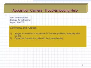
Acquisition Camera: Troubleshooting Help Vern STAHLBERGER Institute for Astronomy August 21-2008 • Comments and Purpose: • Images not centered in Acquisition TV Camera (problems, especially with CSHELL • Create this Document to help with the troubleshooting
Assembly Picture-1 AO Spool AOK-301 Support Structure AOK-300 Top Plate Cover: AOK-317 George Mount AOK-400 (orange colored)
Assembly Picture-2 X-Y Stage (yellow colored)
Assembly Picture-3 AO Spool (partially transparent)
Assembly Picture-4 (Top View) POM (Pick Off Mirror; Movable via X-Y Stage Covers for Acquisition Box removed! Animatics for X-Y Stage
Collins CCD Camera & Focus Mechanism Lens Cell AOK-271 Filter Wheel AOE-100 Fold Mount AOK-205 (Movable) Fold Mount AOK-205 (Fixed) Apogee CCD Camera & Focus Mechanism
Gimbal Mount Pickoff Mirror: AOK-100 AO Spool Some parts partially transparent
POM Mechanism without Support Structure • Mechanism Description: • The Pickoff Mirror Support is a 2-Axis Gimbal Mount Mechanism whose axis are at right angles to each other and are co-planar to the front surface of the Mirror. The nominal angle of the POM is 45 degrees to the incoming beam • CCW and CW Rotation is limited to about 2 degrees (stops) in both axis • Compression Springs are used to preload Gimbal Frames onto Actuator ends (eliminating backlash) • Rotation is accomplished remotely using Newport Actuators (blue cylinders) • Note: This mechanism is difficult to service while installed inside the AO Spool. Remove everything up to, but not including X-Y Stage. (see next slides) • Checklist: • Do Actuator ends remain in contact with the Gimbal Frames at all times? Will require energizing the Actuators to verify • Are the Actuators themselves held firmly in place (check screws that hold Actuator Bodies) • Check Flex Pivots for breakage; check screws that secures Flex Pivots 8x) • Check Mirror Clips 3x (do they hold the POM firmly in place?) • For a parts list of Gimbal Mount Pickoff: AOK-100 go to… • http://irtfweb.ifa.hawaii.edu/~ao/Mechanical/AO-IRTF/AO-Acquisition-Camera-AOK/Assy-AOK/ a b Actuator a-axis Actuator b-axis
Note: To access these screws disassembly is NOT required to what is shown in this picture!! Optics Base Plate: AOK-312 Relevant Screws Qty=4 X-Y Stage George Mount: AOK-400 There are 4x 10-32 Socket Head Cap Screws (SHCS) used to bolt the Optics Base Plate to the X-Y Stage All of them are accessible by removing the Top Plate Cover AOK-317 (see next slides). Side walls do NOT have to be removed!
Access to 1x 10-32 SHCS May need to move motor if not visible