Download
1 / 24
240 likes | 421 Views
T0 offline status. Alla Maevskaya Institute for Nuclear Research, Moscow 8 October 2007 ALICE offline week For T0 group. T0 status Test of T0 electronics by LCS Tools show data for LCS Calibration Reconstruction QA Addendum: how HPTDC works. Outline.

E N D
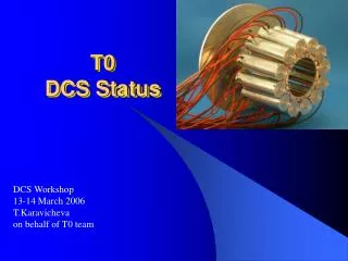
T0 offline status Alla Maevskaya Institute for Nuclear Research, Moscow 8 October 2007 ALICE offline week For T0 group
T0 status Test of T0 electronics by LCS Tools show data for LCS Calibration Reconstruction QA Addendum: how HPTDC works Outline 8 October 2007 Alla Maevskaya INR MoscowALICE offline week
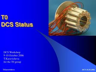
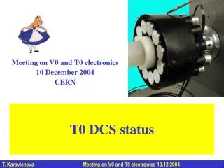
T0-C T0-A Status of T0 T0-C was installed in April and the T0 electronics production was completed in September. Electronics installation and testing will be completed before end 2007. At this moment we are completing the final tests of electronics in the T0 lab with T0-A and we are going to move the electronics to Point 2 to be able to run the detector during the magnet-on period in December. T0-A is now scheduled for installation in Jan/Feb 2008. 8 October 2007 Alla Maevskaya INR MoscowALICE offline week
Configuration during the September 2007 test: Hardware -T0-A detector -Laser system -New shoe-boxes (from F.Formenti) -Fast electronics (final version) -Readout electronics CPDM + TRM + VME64X backplane + DRM (final version) Readout electronics Already tested : -new shoe-boxes -T0 Trigger Unit (T0TU) -Start Laser system from pre-pulser comes from TTC -Busy signal generated by DRM -time & amplitude resolutions -NIM crate control & Thresh. For CFD -new version of TVDC Fast electronics 8 October 2007 Alla Maevskaya INR MoscowALICE offline week
CFD LED 24 Leading Edge Discriminators (LED-CFD amplitude) QTC 48 Charge –to-Time Converter amplitudes meaner (T0A + T0C) /2 QTC full 2 full multiplicities TVDC Trigger: vertex position in given range T0A Trigger: T0A T0C Trigger: T0C central Trigger: central s-centr Trigger: semi-central T0 readout channels 24 Constant Fraction Discriminators (Time) 8 October 2007 Alla Maevskaya INR MoscowALICE offline week
Current electronics test with Laser Calibration System (LCS) The electronics test is running now. Our engineers use AliRoot based tools to see what they measure. The same tool (extended with writing to OCDB) can be used for Laser Calibration Runs in between physics runs. 8 October 2007 Alla Maevskaya INR MoscowALICE offline week
Tools to show spectra from LCS AliT0CalibLaserData file with 105 1D histograms as readout output 24 QTC (QT1-QT0) 24 LED-CFD 24 CFD vs QTC walk correction by QTC 24 CFD vs LED-CFD walk correction by LED OCDB 8 October 2007 Alla Maevskaya INR MoscowALICE offline week
LaserDataViewer Test shows that with full scheme we can provide time resolution 30-40ps 8 October 2007 Alla Maevskaya INR MoscowALICE offline week
What T0 will measure Time when particles from interaction point hit T0 with accuracy 30-40ps ….with time reference synchronized for each T0 channel and TOF Interaction time (TC+TA)/2 that does not depend on vertex position but has the synchronized reference time for T0 and TOF. Can be used directly in number of channel units by TOF as START signal. Resolution of this signal is not worse than 30ps Vertex position with accuracy ~1cm. (TC-TA)/2 can be calibrated to cm units after 1st run using ITS vertex Granted: multiplicity in region 4.61 < η< 4.92 && -3.28< η <-2.97 with good φdivision 8 October 2007 Alla Maevskaya INR MoscowALICE offline week
Calibration procedure Time signal on the exit of CFD channel consists of • time of flight of particles • time delays in cables and electronics unique for each channel and not changing during run • time shift depending on amplitude (walk) Time signals will be equalized on the entrance of OR module for perfect online trigger signals. Time delays of channels on LCS are not the same as for the beam. So equalizing of time delays during data taking can be done only offline using DA information collected during run. TOF Teq D Twalk D 8 October 2007 Alla Maevskaya INR MoscowALICE offline week
Laser calibration • Before 1st run and between runs LCS can: • check channel condition • plot histograms for CFD, LED and QTC • compare with existing in OCDB (Ref) • write in OCDB new one if old was different (QA) • using CFD, LED and QTC data produce 48 TGraphs “Walk correction” • write “Walk correction” to OCDB • write to OCBD scale to convert amplitude signal to MIP’s unit 1MIP ΔTwalk Eval(Amp) 8MIPs Amp 8 October 2007 Alla Maevskaya INR MoscowALICE offline week
Equalizing of channels 10 We decided that PTM1 will be the reference PMT with time T1 Event by event DA fill histograms with ΔTieq = T1-Ti Mean value of ΔTieq spectrum shows only the difference in delays between channels 9 11 Apply walk correction Equalize time delay in channels 8 12 7 1 6 2 5 3 4 If can be possible to read information about 1MIP amplitude range (measured by LCS and written in OCDB) DA can choose only 1Mip signals and will provide information for one step perfect calibration and reconstruction More about DA in Tomek’s presentation 8 October 2007 Alla Maevskaya INR MoscowALICE offline week
Emulation of PYTHIA time and amplitude spectra with LCS Because mean values are equal for 1MIP events and “PYTHIA cocktail” we can use CFD signal without amplitude selection as input for procedure for equalizing channels 1MIP 2MIP Particle multiplicity on the 1 PMT according to PYTHIA p+p@14TeV Time spectra corresponding to 1MIP amplitude 1MIP 2MIP Amplitude spectra of 1&2MIPs generated by LCS Time spectra corresponding to 1&2 MIPs amplitude spectra 8 October 2007 Alla Maevskaya INR MoscowALICE offline week
Calibration parameters in OCDB 8 October 2007 Alla Maevskaya INR MoscowALICE offline week
Calibration parameters in OCDB(ref) And more … about it in Tomek’s presentation 8 October 2007 Alla Maevskaya INR MoscowALICE offline week
Reconstruction Input for reconstruction: after calibration each time channel will be Ti = TCFD + ΔTwalk + Δ Teq • Choose PMT with smallest time on both (A & C) sides T0A & T0C ( or weighted mean – is not clear yet ) • Calculate interaction time (TA+TC)/2 • Vertex position as (TA-TC)/2 • Convert amplitude information to 1, 2…MIPs units 8 October 2007 Alla Maevskaya INR MoscowALICE offline week
2nd step of reconstruction If DA could not choose only 1 MIP particles for calculation ΔTeq we can improve time resolution by 2nd step of reconstruction using data of 1st step for calibration. This improves the time resolution by ~5ps for p+p runs and is necessary for ion+ion runs reconstruction 8 October 2007 Alla Maevskaya INR MoscowALICE offline week
Filling ESD In ESD we have to write for physical issues: • Amplitude for each PMT • Mean time • Vertex position • T0A • T0C 8 October 2007 Alla Maevskaya INR MoscowALICE offline week
QA of reconstruction For our own understanding of reconstruction quality we need for each PMT event-by-event time in number of channels, amplitude (LED and QTC), All 5 trigger signals 24 INT, 48 Float, 5 Bool We can write them in any place from where we can get them and look in: ???? ESD, ESDfriend , QA special place ???? 8 October 2007 Alla Maevskaya INR MoscowALICE offline week
QA of raw data We need QA control of raw data and detector condition immediately after run. This knowledge allows us between runs • understand detector status during run • recalibrate detector if it is necessary • repair something…. Collect by DA CFD, LED and QTC (additional 72 histograms), write to OCDB or RefCDB. After shuttle finish his work we can connect laptop and investigate histograms If Monitoring system will store histograms in the place we can reach them 8 October 2007 Alla Maevskaya INR MoscowALICE offline week
To be done This weekend we more or less finished our discussions about calibration and now we are ready to extend existing codes to fulfill it. In the middle of November T0 offline will be “ready” for the 1st run 8 October 2007 Alla Maevskaya INR MoscowALICE offline week
Start Stop What is a TDC and its use I • TDC's are used to measure time (intervals) with high precision • Start – stop measurement • Measurement of time interval between two events: start signal – stop signal • Used to measure relatively short time intervals with high precision • Like a stop watch used to measure sport competitions From presentation of author of HPTDC
Time scale (clock) Hits What is a TDC and its use II • Time tagging • Measure time of occurrence of events with a given time reference Time reference (Clock) Events to be measured (Hit) • Used to measure relative occurrence of many events on a defined time scale • Such a time scale will have limited range: like 12 hour or 24 hour time scale on your watch when having no date and year • Like a normal watch From presentation of author of HPTDC