Title
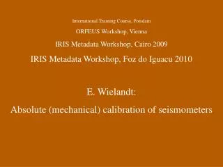
Title. International Training Course, Potsdam ORFEUS Workshop, Vienna IRIS Metadata Workshop, Cairo 2009 IRIS Metadata Workshop, Foz do Iguacu 2010 E. Wielandt: Absolute (mechanical) calibration of seismometers. Systematics. Absolute Calibration.

Title
E N D
Presentation Transcript
Title International Training Course, Potsdam ORFEUS Workshop, Vienna IRIS Metadata Workshop, Cairo 2009 IRIS Metadata Workshop, Foz do Iguacu 2010 E. Wielandt: Absolute (mechanical) calibration of seismometers
Absolute Calibration Except for geophone-type sensors, absolute calibration requires a mechanical motion of the whole instrument („frame input“). It is normally obtained from a shake table. Shake tables are precise only in a frequency band around 1 Hz that does not cover the full bandwidth of broadband sensors. So the frequency response must be measured electrically (over the calibration coil). The absolute calibration then determines the last unknown instrumental parameter, the generator constant or responsivity. It is most easily measured in the middle of the passband.
Passive electromagnetic sensors: When the motion of the seismic mass is linear and its size is known, then the generator constant can be determined electrically, without moving the frame of the instrument. See the old MSOP or the manual of the Sensonics MkIII seismo-meter for a parameter determination based on the transient response („ringdown“) following the interruption a known current through the signal coil. Another method is suggested in the next slide.
The generator constant can also be determined from the numerical damping at different damping resistors. Rd is sum of coil resistance and load resistance.
Swing Why horizontal shake tables are not useful at long periods: Tilt couples gravity into the horizontal components of motion. We illustrate this with a ball sitting on a swing. The ball (representing the seismic mass) would not indicate any motion because the swing is an inertial system.
milling machine The table of a milling machine can provide a well-defined, steplike frame input in three axes. The only auxiliary device is a stop for the handwheel, here realized with a wooden bar and a sawblade. The DISPCAL software evaluates only the start and final positions of the sensor, and is unsensitive to the time-history of the motion. The generator constant is obtained with a precision of 1%.
plot Calibration of an old STS1 (20s) on a milling machine. Top: output signal; center: restored frame velocity; bottom: restored frame displacement. Since the true displacement is known, we can determine the generator constant of the sensor.
plot The method works also with short-period seismometers (here a Sensonics Mk III). However, in this case the free period and damping of the sensor must be known with some precision, so an electrical calibration should be made while the sensor is installed on the milling machine. Top trace: output signal, bottom: restored frame displacement.
balance An ordinary packet balance can serve as an unexpensive vertical step table. It may be necessary to suppress the wobbling horizontal motion with steel ribbons (red) clamped to a fixed block (blue). Further hints are given in the NMSOP (see last slide).
plot Calibration of a 10 Hz geophone on a packet balance. Top: output signal; traces 2 and 4: restored frame velocity; trace 5: a zoom of the „quiet“ sections of trace 4; bottom: restored frame displacement.
For seismometers up to 600 kg this centesimal balance is a perfect step table (OVSICORI-UNA, Heredia, Costa Rica)
tilt lever Horizontal sensors or sensor components can be calibrated with tilt steps. Broadband seismometers may go offscale when the tilt exceeds a few parts in 10 000, but this takes some time. So one can use larger tilts and keep the output within scale by reversing the tilt. The output signal is analyzed with the TILTCAL3 software that is similar to DISPCAL3 but identifies and measures steps of acceleration.
plot A calibration by tilt steps. Top: output signal; trace 2: restored frame velocity; trace 3 and 4: automatic identification of steps; bottom: restored frame acceleration (the transitions have been blanked out).
Why seismometers should be calibrated in situ: some things can be wrong, or go wrong during the installation in a vault, that might not be detected in the lab.We have seen:
and: undocumented or forgotten damping resistors, dividers, even preamps ...
A portable step table for in situ absolute calibration.No need to disconnect and reconnect cables.
The basic design element is an elastic frame that permits only a parallel motion of its sides. Four of these frames connect the top and bottom base-plates (in red) of the table.(side view as in the next slide)
More information: • IASPEI New Manual of Seismological Observatory Practice, ed. P. Bormann, ISBN 3-9808780-0-7, GeoForschungsZentrum Potsdam 2002: chapter 5 • IASPEI International Handbook of Earthquake and Engineering Seismology Part A, ed. W. H. Lee et al., ISBN 0-12-440652-1, Elsevier 2003: chapter 18 • Texts and Software can be downloaded from www.geophys.uni-stuttgart.de/downloads/