Download
1 / 37
380 likes | 519 Views
NSTX. Supported by. Final Design- CS Magnets and Components. James H. Chrzanowski and the NSTX Upgrade Team. College W&M Colorado Sch Mines Columbia U CompX General Atomics INEL Johns Hopkins U LANL LLNL Lodestar MIT Nova Photonics New York U Old Dominion U ORNL PPPL PSI

E N D
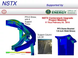
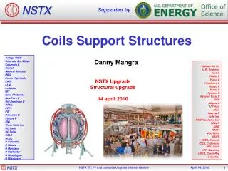
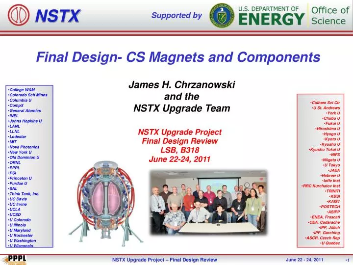
NSTX Supported by Final Design- CS Magnets and Components James H. Chrzanowski and the NSTX Upgrade Team • College W&M • Colorado Sch Mines • Columbia U • CompX • General Atomics • INEL • Johns Hopkins U • LANL • LLNL • Lodestar • MIT • Nova Photonics • New York U • Old Dominion U • ORNL • PPPL • PSI • Princeton U • Purdue U • SNL • Think Tank, Inc. • UC Davis • UC Irvine • UCLA • UCSD • U Colorado • U Illinois • U Maryland • U Rochester • U Washington • U Wisconsin • Culham Sci Ctr • U St. Andrews • York U • Chubu U • Fukui U • Hiroshima U • Hyogo U • Kyoto U • Kyushu U • Kyushu Tokai U • NIFS • Niigata U • U Tokyo • JAEA • Hebrew U • Ioffe Inst • RRC Kurchatov Inst • TRINITI • KBSI • KAIST • POSTECH • ASIPP • ENEA, Frascati • CEA, Cadarache • IPP, Jülich • IPP, Garching • ASCR, Czech Rep • U Quebec NSTX Upgrade Project Final Design Review LSB, B318 June 22-24, 2011 • 1
Outline of Presentation Inner TF Coil Assembly OH Solenoid Center Stack Inconel Casing Ceramic Break Assembly Inner PF Magnets TF Flex Bus Joint Outer TF Coil R&D Activities Drawings and documents Summary
General Arrangement • Umbrella Structure • TF Flex Bus and Support Structure • Centerstack Assembly • Major Centerstack Components • Outer TF Coils • Vacuum Vessel
Upgraded Centerstack Components • Inner PF1c • Inner PF1b • Inner PF1a • Inner TF Bundle • Ohmic Heating Coil • Plasma Facing Components • CS Casing • Ceramic break assembly
Inner TF Design Parameters Inner TF Bundle 15.7 inch diameter w/Lead Extensions
INNER TF CONDUCTOR ASSEMBLY • Material: C10700 –Oxygen free-silver bearing copper conductor Extrusions: Purchased from “Luvata” (COMPLETE) • Lead Extensions: Material-Copper-Chromium-Zirconium • Inner TF Conductor Assy.: Will be handled with a single contract (Award in the June- July 2011) DOE approval has been received • Preliminary machining of conductors • Friction Stir Weld (FSW) Cu-Cr-Zr lead extensions to copper extrusions • Final machine conductors
INNER TF INSULATION and VPI DESCRIPTION • Conductor Preparation: To enhance the shear strength of the insulation to the copper surface pre-requisite steps will be taken. • Grit blast conductor surfaces • Apply primer to surfaces (CTD-450 Cyanate Ester Primer) • Cure cycle: 8 hours @ 110 degrees C • Post Cure Cycle: 4 hours @ 150 degrees C • Insulation: (3-half-lapped layers)0.006 inch thick S-2 (satin weave) standard silane finish glass tape- (Temperature class- 180 degrees C) • Ground wrap Insulation: Half-lapped layers of S-2 glass • VPI System- CTD-425 Cyanate-Ester Hybrid • Cure cycle: 22 hours @ 110 degrees C • Post Cure Cycle: 24 hours @ 170 degrees C
Upper & Lower Crown Assemblies • Purpose: Lock conductors together & help transfer load from TF bundle through lid structure to umbrella • Cooling connections • Kapton/G-10 Flash shields between adjacent joint areas Crown Assembly TF inner Legs • 8
Upper & Lower Crown Assemblies-cont’d • Laminate Crown • Epoxy/S-2 glass construction circumferentially wound (jelly-roll) • Pinned to Inner TF Conductors 316 SS • 9
OH Solenoid Materials • Conductor : C10700 –Oxygen free-silver bearing copper conductor Insulation: • Turn Insulation: Co-wound Kapton/S2 glass tape • Ground wrap Insulation: Half-lapped layers- 0.006 inch thick S-2 (satin weave) standard silane finish glass tape- (Temperature class- 180 degrees C) • Fillers: All G-11 laminate material • Cooling Fittings: Custom cast copper components C10200 • VPI System- CTD-425 Cyanate-Ester Hybrid system • Cure cycle: 22 hours @ 100 degrees C • Post Cure Cycle: 24 hours @ 170 degrees C • 11
OH Solenoid Design Features • The Coil leads are located on the bottom of machine to minimize motion on the leads and bus connections. • Co-axial coil/bus lead design to minimize field errors • In line braze may be required if full conductor lengths are not available (Conform” extrusions is being investigated) • Layer to Layer TIG-braze joints will be used [similar to existing joints]- qualified • Improved cooling fitting assemblies- more stable and resilient • Coil will be wound 2 conductors in-hand around the Inner TF bundle (No tension tube) • 0.100 inch clearance will be maintained between TF and OH coil to allow for thermal growth and motion between coils (further discussed in second presentation) • 12
OH Layer to Layer Joints OH Cooling fittings- torch brazed to copper conductors • G-11 fillers between layers supports turns • S-2 glass between G-11 fillers • Perforations in G-11 will enhance epoxy flow during VPI • Layer to layer TIG-Braze joint [Typical] • “TIG-Braze” • TIG-Brazing method minimizes annealing of conductors (use Sil-Fos) • Provides adequate joint strength • Qualified method and procedures used in previous OH solenoids • 13 NSTX • NSTX Center Stack Upgrade Peer Review • April 29, 2010
OH Solenoid Lead Area • Coil leads are brazed to OH copper conductor • Leads are well supported in structure • 316 Stainless steel and G-11 insulating materials • 14
OH Solenoid End Conditions • Belleville Washer Assembly - designed to maintain vertical pre-load on the OH solenoid at all times • Coaxial bus lead connection • Lower Inner TF leads • Upper OH Coil • Lower OH Coil • 15
Inner Poloidal Field Coils • PF1C Coil • PF1B Coil • PF1A Coil • The inner PF coils will be manufactured by an outside vendor. • 16
Inner PF Coil Parameters 3-Sets of inner PF coils PF1a & 1b wound directly onto support PF1c wound on mandrel then installed into can and VPI’d • 17
Inner PF Coil Materials & Construction • Conductor: • 10700 (ASTM 187) Oxygen free-silver bearing copper conductor w/ cooling hole. • 18
Inner PF Coil Conductor • Insulation Scheme: • Co-wound Kapton w/ S-2 glass tape • VPI System: • CTD-425 Cyanate-Ester Hybrid system • Cure cycle: 22 hours @ 100 degrees C • Post Cure Cycle: 24 hours @ 170 degrees C • Coil Fillers: • G-11 laminate • Structures: • Stainless steel 316 • Construction: • Standard copper tension wound coils • No in line brazes required • Torch braze lead terminals • Outside vendor procurement- includes PF supports, copper conductor and VPI materials • 19
Inner PF Coil Leads • PF-1C • PF-1B • PF-1A • 20
Inner PF Lead Support • Sliding support interface • Insulated SS Support Around leads • Removed lower restraint support • Revised • Original • Analysis has revealed that the inner PF leads need to be supported above the leads. • Leads have been extended & support placed above leads to allow for growth of coil during operation
Center Stack VV Case Design Features • Cooling lines • Bellows • Centerstack casing provides the inner vacuum wall for the NSTX vessel and mounting surface for PFC’s. • 22
Center Stack Casing Components • Organ Pipes for diagnostic wires • Inconel 625 bellows • PFC Mounting • Inconel studs • Tapped holes • Inconel studs • Cooling for Inboard Divertor • Inconel Casing • * Outside vendor procurement • 23
CS Casing Support Structure • CS Casing Support Structure • 24
Ceramic Break Assembly • 316 Stainless Steel Structure • PF-1C Coil • G-7 Insulators • Higher Operating Temperatures 400° • Ceramic Insulating Rings • Viton “O” Rings • 25
Ceramic Break Assembly- “O”-Rings • Active Cooling • Active cooling has been added to support Viton “O” rings during bakeout • Viton “O” ring Locations • Viton “O” rings • Can operate continuously at 204°C • Endure thermal excursion to 315°C • 26
Inner TF Flex Bus Joint • Inconel 718 Studs • TF Flex Bus Assembly (Cu-Cr-Zr) • Heli-Coil inserts • Inner TF Conductor Assembly • Super Nuts • Outer TF Bus Extensions (Cu-Cr-Zr) • 27
Inner TF Flex Bus Joint • Minimum of 2500 psi contact pressure developed across joint • Copper (C10200) Lead Extensions (Upper only) • Outer TF Bus Extensions (Cooled) • Stainless Steel Washer Plates • 28
Flex Joint R&D Verification Tests • 1500 psi pressure sensitive tape shows full surface contact under load • Flex bus has been cycled to over 300,000 cycles (5 x life) • Insert Pull Tests have been successfully completed (42746 lb maximum load) • Maximum load had NO measurable or observable effect on Heli-coil or copper surface • Inconel hardware broke w/o insert failing
TF Flex Bus Hardware • “Super Nut” : • Nut Body: A286 Stainless • Jack Bolts: Inconel 718 • Washer: Inconel 718 • “Stud” : • Thread- 5/8-11 UNC • Material: Inconel 718 • 30
TF Flex Bus Assembly • Material: C18150 Copper Chromium Zirconium • Manufacturing Process: EDM from plate material • Qty: 72 • 31
CHI Bakeout Flags • During bakeout operations, 6000 amps of current flows through the inner vacuum vessel wall. • Three CHI electrical flag connections are located both top & bottom of machine to be used during bakeout. • These are disconnected during NSTX operation. • Air cooled bus connections. • CHI Electrical Flags for Bakeout
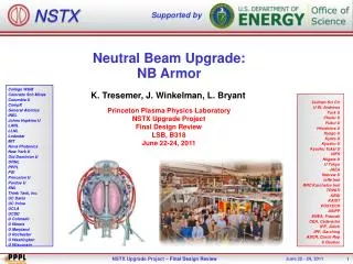
Outer TF Coil • One Outer TF coil assemblies will be replaced during the upgrade shutdown. (Coil #OTF-7) • No change in the physical design is being planned • Insulation scheme will change. • Existing insulation scheme:B-stage insulation (CTD-112) is no longer available • New OTF assembly scheme: CTD-425 the Cyanate Ester hybrid will be used. • Sandblasting and priming: CTD-450 primer • The aluminum support blocks and stainless steel clamps will be reclaimed from the existing OTF and reused on the new coil. • The coil will be built by an outside vendor • PPPL will mount (in-house) the aluminum support blocks and SS clamps • 33
Center Stack Assembly • The assembly of the center stack components will be completed at PPPL. • The next talk will describe in detail the plans and assembly sequence for the center stack. • 34
R&D Activities • R&D Activities to support the design of the upgraded center stack are complete • Selection of VPI system for Inner TF bundle- tests performed by CTD √ complete • Friction Stir Welding (FSW) development for TF conductors- development & tests completed by Edison Welding √ complete • TIG-Braze for OH solenoid Layer to Layer joints- in house √ complete • “Aquapour” qualification program for use during winding OH solenoid- in house √ complete • TF Joint Insert Pull out tests- in house √ complete • TF Flex bus tests- in house √ complete • OH Belleville Washer Tests/verification √ complete • Full size mockup to verify flex buss assembly accessibility - in house √ complete • 35
Drawing & Document Progress • Inner PF Coil:65 drawing approved (100%) • Inner TF Bundle: 28 drawings approved (95%) • OH Solenoid: 39 drawings approved(100%) • Center Stack casing: 33 drawings are complete (98%) • Inner TF Conductor: • Completed conductor Specification (D-NSTX-SPEC-13-128) • Completed Inner TF Conductor Assembly SOW (D-NSTX-SOW-13-133) • In Procurement- presently evaluating proposals • Manufacturing Plan: generated manufacturing plan for the CS components (NSTX-PLAN-MFG-1300-00) • 36
SUMMARY • The design for the Center Stack components have been completed • R&D activities have been completed • In process of approving drawings for CS components • Procured Inner TF copper extrusions • In process of placing purchase order for completing Inner TF coil conductor assemblies. • Inner TF flex bus and joint have been designed and has been supported with R&D tests. • One Outer TF Leg assembly will be fabricated to replace the damaged OTF-7 • 37