Download

1 / 17
170 likes | 353 Views
Chapter 4 EGR 270 – Fundamentals of Computer Engineering. 1. Reading Assignment: Chapter 4 in Logic and Computer Design Fundamentals, 4 th Edition by Mano. Arithmetic Functions Arithmetic functions are important parts of many digital systems.

E N D
Chapter 4 EGR 270 – Fundamentals of Computer Engineering 1 Reading Assignment: Chapter 4 in Logic and Computer Design Fundamentals, 4th Edition by Mano • Arithmetic Functions • Arithmetic functions are important parts of many digital systems. • This chapter will look at components such as: • Adders • Subtractors • Multipliers • Incrementers • Decrementers • As with most of the text, a constant theme is the development of iterative circuits corresponding to reusable functional blocks. • Complements were introduced in Chapter 1. In this chapter we will see that complements are often involved in arithmetic operations.
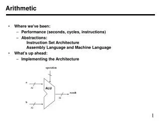
Chapter 4 EGR 270 – Fundamentals of Computer Engineering 2 Binary Adders We will develop binary adders by means of a hierarchical, iterative design. For example, the design of 1-bit adders can be extended to 4-bit adders, 4-bit adder designs can be extended to 16-bit adders, etc. Additionally, we will look at improvements to designs that will significantly increase an adder’s speed. Half-adder – adds 2 bits with no carry in and one carry out. Design a half-adder.
Chapter 4 EGR 270 – Fundamentals of Computer Engineering 3 • Discuss the limitations of a half-adder. • Full-adder– adds 2 bits with one carry in and one carry out • Develop the basic design for the full-adder • Illustrate the SOP implementation • Illustrate the XOR implementation • Show how a full adder can be constructed using two half adders
Chapter 4 EGR 270 – Fundamentals of Computer Engineering 4 4-Bit Adder: Illustrate how a 4-bit adder can be constructed using 4 full adders. 16-Bit Adder: Illustrate how four 4-bit adders can be used to construct a 16-bit adder.
Chapter 4 EGR 270 – Fundamentals of Computer Engineering 5 • Delay problems in binary adders: • One problem with constructing an N-bit adder from N full adders is that the delay becomes excessive. • Each full-adder has to “wait” for the carry out from the previous bit before performing its addition. • We will see shortly that the longest delay path is 2N+2 gate delays for an N-bit adder. • This corresponds to a delay of 34 gates for a 32-bit adder! • We need a better solution: Adding a “look-ahead carry” or “fast carry” circuit to adders will greatly improve their performance. Partial Full-Adder Illustrate how the full-adder can be redrawn as a partial full-adder and a ripple-carry circuit. This is also illustrated for a 4-bit adder on the following page.
Chapter 4 EGR 270 – Fundamentals of Computer Engineering 6 • Partial Full-Adder with Ripple Carry Circuit: • Discuss the delay problems in the circuit below. • We will replace the Ripple Carry Circuit with a Carry Look-Ahead circuit to improve this delay problem.
Chapter 4 EGR 270 – Fundamentals of Computer Engineering 7 Look-Ahead Carry Circuit This is a separate circuit that can generate the carry terms for each of the partial full adders simultaneously. Carry terms can be created in two ways: 1) Generate terms: If Ai = Bi = 1, then Cout = 1. Define Gi = AiBi. 2) Propagate terms: If Ai=1 and Bi=0 or if Ai=0 and Bi=1, then Cout=1 if Cin =1 (or Cout = Cin , or the carry is “propagated”). Define Pi = AiBi. So C1 = G0 + C0P0 (discuss) Also develop expressions for C2, C3, and C4 See how these expressions have been implemented on the following slide.
Chapter 4 EGR 270 – Fundamentals of Computer Engineering 8 • Carry Lookahead Circuit • Ripple Carry is replaced by the Carry Look-Ahead circuit. • Note that C4 is replaced by G0-G3 and P0-P3 for expandability. • The number of gate delays is significantly reduced as seen in the following examples:
Chapter 4 EGR 270 – Fundamentals of Computer Engineering 9 Subtraction using r’s complement: A complement can be used to represent a negative value. It is difficult for a computer to subtract, but relatively simple to add and to find complements. Therefore, it is common to add a complement rather than to subtract. Examples:
Chapter 4 EGR 270 – Fundamentals of Computer Engineering 10 Subtraction using (r-1)’s complement: Subtraction can also be performed using (r-1)’s complements instead of r’s complements as illustrated below. The method above has the disadvantage of requiring one additional step: the addition of the carry bit, C. As a result, this method is not commonly used. Although the text covers this method as well, we will ignore it. We will ignore this method as subtraction using r’s complements is more efficient.
Chapter 4 EGR 270 – Fundamentals of Computer Engineering 11 • Subtraction using 2’s complement with signed numbers: • Signed numbers are represented as follows: • The MSB is the sign bit. • If the MSB = 0, the number is positive. • If the MSB = 1, the number is negative and stored in 2’s complement form. • Example: If each number is represented using 8 bits where the MSB is the • sign bit, determine the value of each number below: • 00001111 • 11110000 • 01010101 • 11111111
Chapter 4 EGR 270 – Fundamentals of Computer Engineering 12 • Example: Represent each number below using 8 bits, where the MSB is the • sign bit: • 12 • -12 • 32 • -32 • Example: Perform various subtractions and additions using pairs of the • numbers in the example above and verify that the results are correct. • 12 + (-32) • 32 + (-12) • -12 – (32) • -32 – (-12)
Chapter 4 EGR 270 – Fundamentals of Computer Engineering 13 Adder-Subtractor Circuit We have seen that subtraction can be performed using 2’s complement addition. The adder-subtractor circuit shown below can perform either addition or subtraction (using 2’s complement addition) as follows: Addition: (S = 0) If S=0, then X3 = B3, so the adder circuit simply adds A and B with C0 = S = 0 (input carry = 0). Subtraction: (S = 1) If S=1, then X3 = B3’, so the adder circuit simply adds A and B’ with C0 = S = 1 (input carry = 1). Since B’ is the 1’s complement of B, adding the 1’s complement + 1 (input) carry is equivalent to adding the 2’s complement of B or subtracting B from A. X1 X0 X3 X2
Chapter 4 EGR 270 – Fundamentals of Computer Engineering 14 Adder-Subtractor Circuit Trace through the circuit below to show that the adder-subtractor circuit works correctly for the following example using 4-bit signed binary numbers (note that the range of allowable values is +7 to -8). Example 1: 7 + (-3) = 4
Chapter 4 EGR 270 – Fundamentals of Computer Engineering 15 Adder-Subtractor Circuit Trace through the circuit below to show that the adder-subtractor circuit works correctly for the following example using 4-bit signed binary numbers (note that the range of allowable values is +7 to -8). Example 2: -6 - (-1) = -5
Chapter 4 EGR 270 – Fundamentals of Computer Engineering 16 • Other Arithmetic Functions • Contraction – Using the result of an existing function or circuit to create a related function or circuit. The text illustrates how the following circuits can be designed using contraction based on existing designs for adders and subtractors: • Incrementer – circuit that adds 1 to input X (example on next slide) • Decrementer – circuit that subtracts 1 from input X • Increment-by-N circuit – a circuit that adds a constant N to input X • Decrement-by-N circuit – a circuit that subtracts a constant N from input X • Multipliers and Dividers • Will not be covered in this course. • The Companion Website for the textbook has a supplement on this topic. • Contraction can also be used on existing multiplier/divider circuit designs to yield circuits that will produce: • Multiplication by a constant • Division by a constant • Decimal Arithmetic • Will not be covered in this course. • The Companion Website for the textbook has a supplement on this topic.
Chapter 4 EGR 270 – Fundamentals of Computer Engineering Contraction – Illustration (Fig 4-9 in textbook) The following diagram from the text illustrates how contraction could be used to modify the design of a 3-bit adder to produce a 3-bit incrementer. Trace through the adder circuit with the input B = 001 to see how the design simplifies to the incrementer circuit shown below (4 gates instead of 15). 17