Download
1 / 12
120 likes | 213 Views
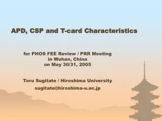
APD, CSP and T-card Characteristics. for PHOS FEE Review / PRR Meeting in Wuhan, China on May 30/31, 2005. Toru Sugitate / Hiroshima University sugitate@hiroshima-u.ac.jp. PHOS electronics embedded. PHOS signal processing scheme. PbW0 4 crystal. lead-tungstate crystal (PWO).

E N D
APD, CSP and T-card Characteristics for PHOS FEE Review / PRR Meeting in Wuhan, China on May 30/31, 2005 Toru Sugitate / Hiroshima University sugitate@hiroshima-u.ac.jp
PbW04 crystal lead-tungstate crystal (PWO) • Inorganic scintillating crystal of 22x22x180 mm3, corresponding to 20X0. • Emission spectrum has blue(420nm) and green(500nm) components. • Light yield of 7-12 pe/MeV for crystals produced in Apatity. • Larger LY as cooling down, but increase slower components. • Fluorescence decay-time of around 25ns at the operation point; i.e. -25deg. High QE in blue, low noise and capacitance, and thin photo-sensor, operational at low temperature and in magnetic field is required.
Smaller sensitive area, but 3-4 times higher QE than PMT. • Abrupt breakdown at a certain reverse voltage. NB; data are given at 25 deg.
Gain depends on temp and reverse voltage, and • higher performance as cooling down. • Both the precise temperature and reverse voltage controls are required.
Breakdown voltage and Op. voltage at M=50 number of APD Inverse current (nA) at op. voltage 300 350 400 450 500 inverse voltage (V) number of APD number of APD 0 10 20 30 40 50 15 20 25 30 Reality of APD’s (for samples ~ 1800) • Vop.= 350 - 440V • Vbreak – Vop.= 20 - 25V • Idark peaks at 5nA, and mostly below 15nA. Vbreak–Vop. Inverse current (nA) voltage difference (V)
APD: Hamamatsu S8148/S8664-55 • APD preamplifier: • Originally designed and built at CCNU & Bergen. • Re-designed in 2002 at Hiroshima using components available in Japan. • Hiroshima ver.2 is successfully performed in PHOS256 in 2003/04. • Minor modification for ver.3 in 2004. • 5,000 of Hiroshima ver.3 has been produced for the first module. C5 only for test 100M // 1pF
Connectors onboard; MOLEX 53047-0610 AMP 747470-2 • T-card: • 8 CSP outputs into single base connector. • Originally built at Bergen in 2003. • Re-deigned at Hiroshima in 2005 to; • fit with the new frame design at Sarov, • remove a test pulse generator, and • remove serial registers R11 to R16 in power lines, since they are on CSP. • 10 samples of the new version for testing. Sarovdesign