Download
1 / 1
50 likes | 392 Views
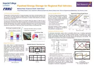
Ragone Plot of Energy Storage Devices. Braking times HST LU train. Batteries. High-speed flywheels. Super- capacitors. Electrolytic capacitors. Film caps. Rail Energy Consumption by Type. Relatively small station spacing, low speed Hydrodynamic transmissions.

E N D
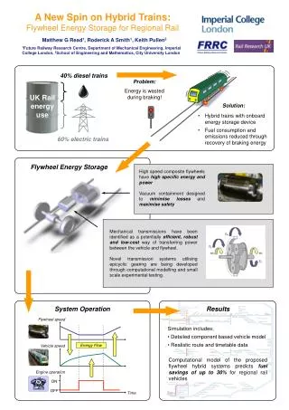
Ragone Plot of Energy Storage Devices • Braking times • HST • LU train Batteries High-speed flywheels Super- capacitors Electrolytic capacitors Film caps Rail Energy Consumption by Type • Relatively small station spacing, low speed • Hydrodynamic transmissions Typical Energy Usage Simulation Results for Discharge/Charge Cycle (assuming no transmission losses) Source: ‘Improving the efficiency of traction energy use’, RSSB report, 2007 Vehicle Flywheel SESS Flywheel Energy Storage for Regional Rail Vehicles FRRC Matthew Read1, Roderick A Smith1, Keith Pullen2 1Future Railway Research Centre, Department of Mechanical Engineering, Imperial College London, 2School of Engineering and Mathematics, City University London UK Rail Energy Consumption Transportation currently accounts for a large percentage of total carbon dioxide emissions in the UK. Concerns over global warming, increasing fuel prices and energy security are driving the development of new technologies with the potential to increase vehicle efficiency and reduce primary energy consumption. The use of an electrical supply network for rail vehicles allows the system to make full use of developments in the field of clean electricity production, and enables simple recovery of braking energy. Diesel powered trains, however, are widely used and account for around forty percent of the total UK rail energy consumption. Improving the efficiency of this type of vehicle therefore represents an opportunity to reduce both carbon dioxide emissions and operating costs. • Energy Storage System • The choice of energy storage device is key to hybrid system performance. A Ragone plot can be used to identify appropriate devices on the basis of specific energy and power. Other considerations include: • system requirements of device • cost, reliability and lifespan • ease of integration with vehicle platform • aims of power control strategy • High-speed flywheels combine a range of advantages; our research is investigating their potential for rail applications. Mechanical Flywheel System A mechanical transmission system offers a potentially efficient way of enabling regenerative braking with the high specific energy and power of flywheel storage. It is proposed that a simple gearbox incorporating a planetary gear set (PGS) can be used with a small secondary energy storage system (SESS) to allow efficient and rapid charging and discharging of the flywheel. The configuration and operation of the system is illustrated below. Schematic Diagram of Proposed System Hybrid Rail Vehicles High inertia losses for diesel-hydrodynamic trains indicate that regenerative braking can significantly reduce fuel consumption. A simple strategy is to use stored energy to provide initial vehicle acceleration, reducing inefficient transmission operation and engine idling while stationary. Simulated fuel savings for a system capable of accelerating the vehicle to 80km/h are shown below as a function of station spacing. Simulation Results for Typical Duty Cycle • SESS provides initial acceleration before discharging flywheel • Flywheel stores 85% of total energy • 82% of flywheel energy passes directly through PGS to vehicle A detailed component based model of the flywheel system has been developed (using a hydraulic SESS) which predicts a round-trip efficiency of around 75%. An experimental test-rig will be used to validate system performance for representative duty cycles, and will allow investigation of alternative configurations. Contact details Email: m.read06@imperial.ac.uk Tel: +44 (0)20 7594 7203