Lecture 9 - Flexure
Lecture 9 - Flexure. June 20, 2003 CVEN 444. Lecture Goals. Load Envelopes Resistance Factors and Loads Design of Singly Reinforced Rectangular Beam Unknown section dimensions Known section dimensions. Moment Envelopes.

Lecture 9 - Flexure
E N D
Presentation Transcript
Lecture 9 - Flexure June 20, 2003 CVEN 444
Lecture Goals • Load Envelopes • Resistance Factors and Loads • Design of Singly Reinforced Rectangular Beam • Unknown section dimensions • Known section dimensions
MomentEnvelopes The moment envelope curve defines the extreme boundary values of bending moment along the beam due to critical placements of design live loading. Fig. 10-10; MacGregor (1997)
MomentEnvelopes Example Given following beam with a dead load of 1 k/ft and live load 2 k/ft obtain the shear and bending moment envelopes
MomentEnvelopes Example Use a series of shear and bending moment diagrams Wu = 1.2wD + 1.6wL Moment Diagram Shear Diagram
MomentEnvelopes Example Use a series of shear and bending moment diagrams Wu = 1.2wD + 1.6wL (Dead Load Only) Moment Diagram Shear Diagram
MomentEnvelopes Example Use a series of shear and bending moment diagrams Wu = 1.2wD + 1.6wL Moment Diagram Shear Diagram
MomentEnvelopes Example The shear envelope
MomentEnvelopes Example The moment envelope
Flexural Design of Reinforced Concrete Beams and Slab Sections Analysis Versus Design: Analysis: Given a cross-section, fc , reinforcement sizes, location, fy compute resistance or capacity Design: Given factored load effect (such as Mu) select suitable section(dimensions, fc, fy, reinforcement, etc.)
Flexural Design of Reinforced Concrete Beams and Slab Sections ACI Code Requirements for Strength Design Basic Equation: factored resistance factored load effect Ex.
ACI Code Requirements for Strength Design Mu = Moment due to factored loads (required ultimate moment) Mn = Nominal moment capacity of the cross-section using nominal dimensions and specified material strengths. f = Strength reduction factor (Accounts for variability in dimensions, material strengths, approximations in strength equations.
Flexural Design of Reinforced Concrete Beams and Slab Sections Required Strength (ACI 318, sec 9.2) U = Required Strength to resist factored loads D = Dead Loads L = Live loads W = Wind Loads E = Earthquake Loads
Flexural Design of Reinforced Concrete Beams and Slab Sections Required Strength (ACI 318, sec 9.2) H = Pressure or Weight Loads due to soil,ground water,etc. F = Pressure or weight Loads due to fluids with well defined densities and controllable maximum heights. T = Effect of temperature, creep, shrinkage, differential settlement, shrinkage compensating.
Factored Load Combinations U = 1.2 D +1.6 L Always check even if other load types are present. U = 1.2(D + F + T) + 1.6(L + H) + 0.5 (Lr or S or R) U = 1.2D + 1.6 (Lr or S or R) + (L or 0.8W) U = 1.2D + 1.6 W + 1.0L + 0.5(Lr or S or R) U = 0.9 D + 1.6W +1.6H U = 0.9 D + 1.0E +1.6H
Resistance Factors, f - ACI Sec 9.3.2 Strength Reduction Factors [1] Flexure w/ or w/o axial tension The strength reduction factor, f, will come into the calculation of the strength of the beam.
Resistance Factors, f - ACI Sec 9.3.2 Strength Reduction Factors [2] Axial Tension f = 0.90 [3] Axial Compression w or w/o flexure (a) Member w/ spiral reinforcement f = 0.70 (b) Other reinforcement members f = 0.65 *(may increase for very small axial loads)
ACI Sec 9.3.4 f factors for regions of high seismic risk Resistance Factors, f - ACI Sec 9.3.2 Strength Reduction Factors [4] Shear and Torsion f = 0.75 [5] Bearing on Concrete f = 0.65
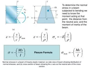
Background Information for Designing Beam Sections 1. Location of Reinforcement locate reinforcement where cracking occurs (tension region) Tensile stresses may be due to : a ) Flexure b ) Axial Loads c ) Shrinkage effects
Background Information for Designing Beam Sections 2. Construction formwork is expensive - try to reuse at several floors
Background Information for Designing Beam Sections 3. • Beam Depths • ACI 318 - Table 9.5(a) min. h based on l (span) (slab & beams) • Rule of thumb: hb (in) l (ft) • Design for max. moment over a support to set depth of a continuous beam.
Background Information for Designing Beam Sections 4. Concrete Cover Cover = Dimension between the surface of the slab or beam and the reinforcement
Concrete Cover Why is cover needed? [a] Bonds reinforcement to concrete [b] Protect reinforcement against corrosion [c] Protect reinforcement from fire (over heating causes strength loss) [d] Additional cover used in garages, factories, etc. to account for abrasion and wear. 4. Background Information for Designing Beam Sections
Background Information for Designing Beam Sections • Minimum Cover Dimensions (ACI 318 Sec 7.7) • Sample values for cast in-place concrete • Concrete cast against & exposed to earth - 3 in. • Concrete (formed) exposed to earth & weather No. 6 to No. 18 bars - 2 in. No. 5 and smaller - 1.5 in
Background Information for Designing Beam Sections • Minimum Cover Dimensions (ACI 318 Sec 7.7) • Concrete not exposed to earth or weather - Slab, walls, joists No. 14 and No. 18 bars - 1.5 in No. 11 bar and smaller - 0.75 in - Beams, Columns - 1.5 in
5. Bar Spacing Limits (ACI 318 Sec. 7.6) - Minimum spacing of bars - Maximum spacing of flexural reinforcement in walls & slabs Max. space = smaller of Background Information for Designing Beam Sections
Minimum Cover Dimension Interior beam.
Minimum Cover Dimension Reinforcement bar arrangement for two layers.
Minimum Cover Dimension ACI 3.3.3 Nominal maximum aggregate size. - 3/4 clear space - 1/3 slab depth - 1/5 narrowest dim.
Example - Singly Reinforced Beam Design a singly reinforced beam, which has a moment capacity, Mu = 225 k-ft, fc = 3 ksi, fy = 40 ksi and c/d = 0.275 Use a b = 12 in. and determine whether or not it is sufficient space for the chosen tension steel.
Example - Singly Reinforced Beam From the calculation of Mn
Example - Singly Reinforced Beam Select c/d =0.275 so that f =0.9. Compute k’ and determine Ru
Example - Singly Reinforced Beam Calculate the bd 2
Example - Singly Reinforced Beam Calculate d, if b = 12 in. Use d =22.5 in., so that h = 25 in.
Example - Singly Reinforced Beam Calculate As for the beam
Example - Singly Reinforced Beam Chose one layer of 4 #9 bars Compute r
Example - Singly Reinforced Beam Calculate rmin for the beam The beam is OK for the minimum r
Example - Singly Reinforced Beam Check whether or not the bars will fit into the beam. The diameter of the #9 = 1.128 in. So b =12 in. works.
Example - Singly Reinforced Beam Check the height of the beam. Use h = 25 in.
Example - Singly Reinforced Beam Find a Find c
Example - Singly Reinforced Beam Check the strain in the steel Therefore, f is 0.9
Example - Singly Reinforced Beam Compute the Mn for the beam Calculate Mu
Example - Singly Reinforced Beam Check the beam Mu = 225 k-ft*12 in/ft =2700 k-in Over-designed the beam by 6% Use a smaller c/d ratio