Download
1 / 22
220 likes | 448 Views
Operator Control Units (OCUs) for the Dismounted Soldier. Concurrent Design Approaches Tank Automotive, Research, Development, and Engineering Center (TARDEC) Carnegie Mellon University, Field Robotics Center. UNCLASSIFIED.

E N D
Operator Control Units (OCUs) for the Dismounted Soldier Concurrent Design Approaches Tank Automotive, Research, Development, and Engineering Center(TARDEC) Carnegie Mellon University, Field Robotics Center UNCLASSIFIED Tank-Automotive Research, Development & Engineering Center
TARDEC OCU Model Robert KaniaPhone: (586) 574-5696Fax: (586)-574-8684Email: kaniar@tacom.army.mil Philip FrederickPhone: (586) 574-6840Fax: (586) 574-8684Email: frederip@tacom.army.mil Vetronics Robotic Mobility Team6501 E.Eleven Mile Rd. Vetronics Technology Area (AMSTA-TR-R, Mailstop 264) Warren, MI 48397-5000
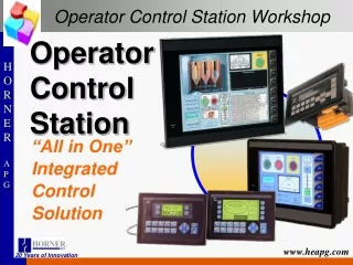
OCU Development Concept • Control a known robotic entity from a PDA interface • Tele-op, Follower, Debug capabilities • Model work of VTI contractor • Similar hardware/concept • Develop in-house expertise
OCU Key Features • Windows CE Operating System • Can Program using Visual Basic with AppForge Mobile VB • Intuitive Windows interface • Hardware • Dual PC Card Expansion Pack • Serial and USB interface
Hardware Architecture • Compaq IPAQ 3850 • Dual-Slot PC Card Expansion Pack • Communications • SMC 2.4 Ghz 802.11b wireless Ethernet • Navigation • Teletype PC Card GPS receiver
Software Architecture Modes of Operation Pendant Null Manual Tele-op Follower Automatic Traffic Cop Command & Control Modes of Operation Null Direct Drive Way point Segmented Hybrid Pocket Client (PKTC) Mobility System Digital Analog Card(DAC) Camera System DAC Non-Contact Optical Sensor Digital Compass DGPS DAC PKTC Mobility System
OCU Tele-operation • Control mobile robot from short distance at non-LOS locations • Percentage-Based Drive Control • On-Screen vehicle video, orientation, location, battery life, and velocity displays
OCU Follower • Operator Drops GPS breadcrumbs while traversing a path for the mobile robot to follow • Set time and distance offset • Operator does not need to interact with PDA
Lab Robot Main Control Panel Wireless LAN GPS Web Cams Hardware Override LADAR External Power Inlet (110VAC) Datron 5th Wheel Breaker & Fuse Panel Computer Interface Panel Power Switching Bus
OCU Conclusions • Tele-operational control is resource intensive and requires faster processor and network communication • Leader/Follower capability is realistic with COTS OCUs • Ruggedization of COTS PDA would be required for any fielded operation
Operator Focused Autonomous Robot Control Scott Thayer & Bill Ommert Carnegie Mellon University, Field Robotics Center
System Hardware Architecture • Compaq iPAQ • modified desk cradle • PCMCIA expansion sleeve • Communications • Wireless Ethernet • Localization • Garmin 16a marine GPS • Point Research Corp. Dead Reckoning Module (DRM)
System Software Architecture • Model View Controller (MVC) architecture • Widely accepted as a good model for interface application design • Allows “skinning” of the application without affecting the data handling or control flow
Control Interface • Use native interface mechanisms • Tap and Hold • Context Menus • Interface must be consistent regardless of application state
Control Interface: Robot • Supports all basic Display configuration options • Allow Max Speed to be set • Autonomous Follow • Autonomous Goto • Stop
Dismount OCU Tradeoffs • Screen size vs. Portability • Level of map detail available to the user vs. runtime of the system • Runtime vs. System Weight • Stateless interface vs. complexity of control
Work at McGregor Range • Dismount OCU integrated with GDRS XUV robot • Robotic following • Used for multiple hours in path following. • Traverses of .5 kilometer through desert terrain.
Results: OCU Interface • Orientation can be hard to discern from the maps quickly. • OCU should provide a non-visual alert cue so that user doesn’t have to constantly watch the display. • Each Entity should have a unique path color. • Text layout should be smarter to avoid overwriting.
Results: OCU Hardware • COTS parts are power hungry • Problems in strong sun • Screen visibility • IR sensor interference • iPAQ has limited expandability • 2 PCMCIA slots which must be local to the iPAQ • One serial port • One USB port without a root hub