Understanding Electric Fields, Resistance, and Capacitors in Circuit Theory
This article delves into the principles of electric fields and their impact on charged objects, detailing how charges accelerate and work is done through potential difference. It also covers the internal resistance of power supplies, how 'lost volts' occur, and the significance of EMF in circuits. Furthermore, we explore capacitors, their functions in circuits, energy storage, and their role in alternating current systems and amplification. Concepts such as Wheatstone Bridge and operational amplifiers will also be discussed to provide a comprehensive overview.

Understanding Electric Fields, Resistance, and Capacitors in Circuit Theory
E N D
Presentation Transcript
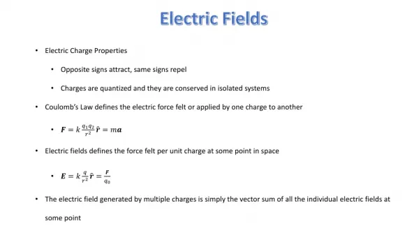
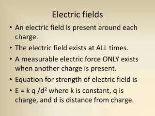
Electric Fields A charged object experiences a force inside an electric field
Electric Fields • The field does work on charged objects • Charges accelerate • W = Q x V
Potential Difference • Work done to move 1 coulomb of charge • 1V = 1 J C-1
Internal Resistance Internal resistance, r E.m.f. ( E ) Current, I E = I.R + I.r Load, R
Internal Resistance • Resistance of power supply itself • work is done to push charges through power supply hence ‘Lost Volts’ • E.M.F. Maximum energy to push unit charge around circuit • Terminal potential difference , work to push unit charge through external circuit ( load )
Internal Resistance • E = V t.p.d. + V lost • V t.p.d. = E - V lost V t.p.d = E - I x r V t.p.d E.M.F open circuit p.d. NO lost volts - slope = r I Short circuit current E = V lost
Wheatstone Bridge R2 R1 R3 R3 R4
Wheatstone Bridge • At balance point For out of balance bridge V r
Alternating Current Peak Voltage r.m.s. voltage
Alternating Current Resistance is independent of frequency
Capacitors • Dielectric 0 V + 5V Charge builds up on plates ( does not flow through dielectric ) 1 F = 1 C V-1
Capacitors • Work is done charging up Capacitor • Energy ( charge) is stored in Capacitor • Ee = 0.5.Q.V Q V Area under graph = Energy Stored Slope = Capacitance
Capacitors • Capacitors block d.c. yet pass a.c • Capacitors supply time delays • Capacitors used to smooth a.c. • Capacitors used as microphones
Capacitors • I directly proportional to frequency I f
Op Amps • Voltage Amplifier • Ideal Op Amp a) Input current = 0 A • b) p.d. across inverting and non inverting pin = 0V
Op Amps : Inverting Mode Rf Rin Vin Vout
Op Aps : Inverting Mode • Saturation occurs at c.a. 85 % of p.supply voltage Vout Vin
Op Amps : Summing Amp 2 inputs can be added together
Op Amps :Differential Mode • Difference between two inputs is amplified Rf R4 Rin Vout R3 V1 V2
Op Amps :Differential Mode • Can be connected to a wheatstone bridge • Used in ECG to subtract the 50 Hz mains hum from the heart signal
Op Amps : Output • Output current is of micro amp order • To drive a speaker or motor a power amp must be used I.e. an NPN transistor or a MOSFET transistor • This increases the current
Op Amps : Output NPN is switched on by output from op amp