Download
1 / 29
290 likes | 440 Views
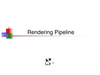
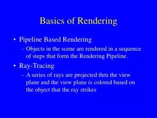
Basics of Rendering. Pipeline Based Rendering Objects in the scene are rendered in a sequence of steps that form the Rendering Pipeline. Ray-Tracing A series of rays are projected thru the view plane and the view plane is colored based on the object that the ray strikes. Scene Definitions.

E N D
Basics of Rendering • Pipeline Based Rendering • Objects in the scene are rendered in a sequence of steps that form the Rendering Pipeline. • Ray-Tracing • A series of rays are projected thru the view plane and the view plane is colored based on the object that the ray strikes
Scene Definitions Camera View Frustrum View Plane Objects/Models
Transform Illuminate Transform Clip Project Rasterize Model & CameraParameters Rendering Pipeline Framebuffer Display Pipeline Rendering
Rendering: Transformations • So far, discussion has been in screen space • But model is stored in model space(a.k.a. object space or world space) • Three sets of geometric transformations: • Modeling transforms • Viewing transforms • Projection transforms
The Rendering Pipeline: 3-D Scene graphObject geometry ModelingTransforms LightingCalculations ViewingTransform Clipping ProjectionTransform
The Rendering Pipeline: 3-D Scene graphObject geometry • Result: • All vertices of scene in shared 3-D “world” coordinate system ModelingTransforms LightingCalculations ViewingTransform Clipping ProjectionTransform
Y X Z Rendering: Transformations • Modeling transforms • Size, place, scale, and rotate objects and parts of the model w.r.t. each other • Object coordinates world coordinates Y Z X
The Rendering Pipeline: 3-D Scene graphObject geometry • Result: • Scene vertices in 3-D “view” or “camera” coordinate system ModelingTransforms LightingCalculations ViewingTransform Clipping ProjectionTransform
Rendering: Transformations • Viewing transform • Rotate & translate the world to lie directly in front of the camera • Typically place camera at origin • Typically looking down -Z axis • World coordinates view coordinates
The Rendering Pipeline: 3-D Scene graphObject geometry • Result: • 2-D screen coordinates of clipped vertices ModelingTransforms LightingCalculations ViewingTransform Clipping ProjectionTransform
Rendering: Transformations • Projection transform • Apply perspective foreshortening • Distant = small: the pinhole camera model • View coordinates screen coordinates
Rendering: Transformations • Perspective Camera • Orthographic Camera
¢ q - q é ù é ù é ù X cos sin X = ê ú ê ú ê ú ¢ q q Y sin cos Y ë û ë û ë û Rendering: Transformations • All these transformations involve shifting coordinate systems (i.e., basis sets) • That’s what matrices do… • Represent coordinates as vectors, transforms as matrices • Multiply matrices = concatenate transforms!
Rendering: Transformations • Example: Rotate point [1,0]T by 90 degrees CCW (Counter-clockwise) y (1,0) x y (0,1) x
Pipeline Rasterization • Take a collection of 2D Polygonal Objects and draw them onto a framebuffer. • Rasterization of Polygons is very efficient. • All Models are eventually converted into polygons for rasterization. • So why use other models? – Next class.
Rasterizing Polygons • In interactive graphics, polygons rule the world • Two main reasons: • Lowest common denominator for surfaces • Can represent any surface with arbitrary accuracy • Splines, mathematical functions, volumetric isosurfaces… • Mathematical simplicity lends itself to simple, regular rendering algorithms • Like those we’re about to discuss… • Such algorithms embed well in hardware
Rasterizing Polygons • Triangle is the minimal unit of a polygon • All polygons can be broken up into triangles • Convex, concave, complex • Triangles are guaranteed to be: • Planar • Convex • What exactly does it mean to be convex?
Convex Shapes • A two-dimensional shape is convex if and only if every line segment connecting two points on the boundary is entirely contained.
Triangularization • Convex polygons easily triangulated • Concave polygons present a challenge
Rasterizing Triangles • Interactive graphics hardware commonly uses edge walking or edge equation techniques for rasterizing triangles
Edge Walking • Basic idea: • Draw edges vertically • Interpolate colors down edges • Fill in horizontal spans for each scanline • At each scanline, interpolate edge colors across span
Edge Walking: Notes • Order three triangle vertices in x and y • Find middle point in y dimension and compute if it is to the left or right of polygon. Also could be flat top or flat bottom triangle • We know where left and right edges are. • Proceed from top scanline downwards • Fill each span • Until breakpoint or bottom vertex is reached • Advantage: can be made very fast • Disadvantages: • Lots of finicky special cases
Edge Walking: Disadvantages • Fractional offsets: • Be careful when interpolating color values! • Beware of gaps between adjacent edges • Beware of duplicating shared edges
General Polygon Rasterization • Now that we can rasterize triangles, what about general polygons? • We’ll take an edge-walking approach
General Polygon Rasterization • Consider the following polygon: • How do we know whether a given pixel on the scanline is inside or outside the polygon? D B C A E F
Polygon Rasterization • Inside-Outside Points
Polygon Rasterization • Inside-Outside Points
General Polygon Rasterization • Basic idea: use a parity test for each scanline edgeCnt = 0; for each pixel on scanline (l to r) if (oldpixel->newpixel crosses edge) edgeCnt ++; // draw the pixel if edgeCnt odd if (edgeCnt % 2) setPixel(pixel);
General Polygon Rasterization • Count your vertices carefully • Details… G F I H E C J D A B