Download
1 / 27
300 likes | 584 Views
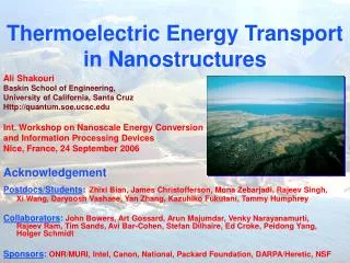
Thermoelectric Energy Transport in Nanostructures. Ali Shakouri Baskin School of Engineering, University of California, Santa Cruz Http://quantum.soe.ucsc.edu Int. Workshop on Nanoscale Energy Conversion and Information Processing Devices Nice, France, 24 September 2006 Acknowledgement

E N D
Thermoelectric Energy Transport in Nanostructures Ali Shakouri Baskin School of Engineering, University of California, Santa Cruz Http://quantum.soe.ucsc.edu Int. Workshop on Nanoscale Energy Conversion and Information Processing Devices Nice, France, 24 September 2006 Acknowledgement Postdocs/Students:Zhixi Bian, James Christofferson, Mona Zebarjadi, Rajeev Singh, Xi Wang, Daryoosh Vashaee, Yan Zhang, Kazuhiko Fukutani, Tammy Humphrey Collaborators: John Bowers, Art Gossard, Arun Majumdar, Venky Narayanamurti, Rajeev Ram, Tim Sands, Avi Bar-Cohen, Stefan Dilhaire, Ed Croke, Peidong Yang, Holger Schmidt Sponsors:ONR/MURI, Intel, Canon, National, Packard Foundation, DARPA/Heretic, NSF
Motivation: Microprocessor Evolution Electronic/Optoelectronic devices → Generate high/ localized heat density
Electrical Thermal Optical Magnetic Mechanical Chemical/biological Direct Conversion of Heat into Electricity Possible Applications • Waste heat recovery • Electric power generator with no moving part • Microscale power sources Significant amount of heat generated as by product of any energy conversion.
Rejected Energy 61% Total 91.4 quad (↑ x3) 1950
T2 T1 b a a V Peltier and Seebeck Effects Q Q b Peltier: a a I Thomson: Seebeck: Commercial TE Module • DT=72C • Cooling density <10W/cm2 • Efficiency 6-8% of Carnot RTGs (space power)
Efficiency of TE Power Generation ZT= 1.2-3.6 ZT = 0.3-0.9 Efficiency (COP) depends on a single ratio (Z)
Superlattices/ Quantum Dot Thermoelectrics T. C. Harman (2002) and R. Venkatasubramanian (2001) PbTe/PbTeSe Quantum Dot Superlattices Ternary: ZT=1.3-1.6 Quaternary: ZT=2 DT=43.7 K, Bulk DT=30.8 K T.C. Harman, Science, 2002 DT=32.2 K, ZT ~2-2.4 R. Venkatasubramanian, Nature, 2001 PbTe/PbSeTe Bi2Te3/Sb2Te3 Superlattice Bulk Nanostructure Bulk Power Factor (mW/cmK2) 25.5 28 40 50.9 Thermal Conductivity (W/mK) 0.5 2.0 0.5 1.26 In-plane geometry Cross-plane geometry (From M. S. Dresselhaus, Rohsenow Symposium, 2003)
Thermionic Emission for Energy Conversion Energy Hot electron Cold electron Cold Hot CathodeBarrierAnode Metal/Semiconductor Superlattice, Embedded Nanostructures Metal/ Deg. Semicond Metal/ Deg. Semicond Solid-State Vacuum Low work function Vacuum (ions) Low work function • Selective emission of hot electrons over a potential barrier can generate electrical power from temperature difference • Thermodynamic reverse process: evaporative cooling of electrons
Si/SiGeC Superlattice Structures for Heterostructure Thermionic Filtering Funded by ONR and DARPA/ARMY HERETIC Si Cathode Cold Electron Hot Electron Si Si0.89Ge0.1C0.01 150x SiGeC/Si Superlattice (10nm/10nm) Barrier • MBE Grown 5” Substrate • Material and Processing Compatible with SiGe HBTs. 1 µm Si (001) Substrate Anode X. Fan, E.Croke, J.E. Bowers, A. Shakouri, et al., “SiGeC/Si superlattice micro cooler,” Applied Physics Lett. 78 (11), 2001. Featured in Nature Science Update, Physics Today, AIP April 2001
Microrefrigerator on a chip • Maximum cooling: 4C (300K), 12 (500K) • Cooling power density: >500 W/cm2 • Response time: < 20-40ms • Materials: SiGe, SiGeC, InGaAs, InP • Fabrication: IC compatible High resolution thermal imaging • Temperature resolution: 0.006oC • Spatial resolution: submicron ZT~0.08-0.1 Thermal imaging camera; J. Christofferson, A. Shakouri, Review of Scientific Instruments Feb 2005. Nanoscale heat transport and microrefrigerators on a chip; A. Shakouri, Proceedings of IEEE, 2006
How to improve ZT? S2s S I J. Snyder (2003) http://www.its.caltech.edu/~jsnyder/thermoelectrics/science_page.htm For almost all materials, if doping is increased, electrical conductivity increases but Seebeck coefficient is reduced.
Metallic Superlattices for Thermionic Energy Conversion Energy Energy Ebarrier Ef High doping Ef Ef Low doping Density of States Distance Doped Bulk Semiconductor/ Metal Highly-Doped Tall Barrier Superlattice Symmetry of DOS near Fermi energy is the main factor determining Seebeck coefficient.
ZT for metallic superlattices with non-planar barriersThermionic Energy Conversion Center MURI Assume: blattice=1W/mK, mobility ~10 cm2/Vs Hot and cold electrons in equilibrium Hot electron filter Non-planar Barrier UCSC Berkeley Harvard MIT NCSU Purdue UCSB Director: A. Shakouri Planar Barrier D. Vashaee., A. Shakouri, Physical Review Letters March 12, 2004 Planar barriers are not ideal for hot electron filtering. ZT>5 is possible with metallic structures with non-planar barriers. Program Manager: Mihal Gross
TEM/HAADF of Semimetallic ErAs Nanoparticles in InGaAs Matrix As In,Ga Er HAADF 1nm STEM images show that the ErAs particles have the rock salt structure. The As sublattice is continuous across the interface. 110 D. O. Klenov, D. C. Driscoll, A. C. Gossard, S. Stemmer, Appl. Phys. Lett. 86, 111912 (2005) 001
Thermal Conductivity of ErAs:In0.53Ga0.47As In0.53Ga0.47As In0.53Ga0.47As 0.4 ML 40 nm 0.1 ML 10 nm 0.3 % ErAs 3.0 % ErAs 3.0 % ErAs:In0.53Ga0.28Al0.19As Kim et al., Physical Review Letters, 30, 045901 (2006)
Sample 1 1E19 Sample 2 4E18 Sample 3 2E18 20nm n-InGaAs Cap layer 10nm InGaAlAs 20nm n-InGaAs/ErAs 0.3% 50nm 5E18 n-InGaAs n-InP substrate ErAs: InGaAs/InGaAlAs SL 70x Add superlattice energy filtering to increase the thermoelectric power factor. Joshua Zide, Daryoosh Vashaee, Gehong Zeng et al., submitted to PRB 2006
Theoretical ZT ZT 1e19 cm-3 6e18 cm-3 2e18 cm-3 Temperature (K) Cross-plane/ In-plane Seebeck Characterization Theory/Experiment Seebeck II, ┴ (300K) ErAs: InGaAs/InGaAlAs Superlattices J. Zide et al., (UCSB, UCSC) submitted to Physical Review B, 2006
Thermoelectric single element characterization Heater Ceramic rails (insulating) 5 • ErAs (SL+substrate) • SiGe (SL+substrate) • BiTe (bulk) 4 OFHC copper 3 Power density (W/cm2) TE sample V+ Thot 2 OFHC copper V- 1 Al cold plate 0 Chilled water 0 50 100 150 200 250 300 350 DT (K) • ErAs generates significantly more power despite the lower effective Seebeck • BiTe degrades rapidly at higher temperatures while ErAs improves with temperature 160x(10nm (InGaAs)0.6(InAlAs)0.4/20nm (n-InGaAs)0.97Er0.03) on 474 mm doped InP substrate 200x(75Å SiGe0.16/ 75Å SiGe0.24) on 403 mm doped Si substrate Peter Meyer, Rajeev Ram (MIT)
Thin film array generator 200 n-p couples, 5-10 microns ErAs:InGaAs/InAlAs superlattice thin films, 120x120mm2, 12 ohm load G. Zeng, J. Bowers, et al. (UCSB) Appl. Physics Letters 2006
Barrier (main-layer) Cathode contact layer Anode contact layer Hot Source Cathode Heat Sink Anode Bias InGaAs InGaAsP InGaAs Monte Carlo + Poisson Equation Goal: Range of validity for thermoelectric and thermionic transport formalisms + Electron-phonon energy exchange (S) Mona Zebarjadi, Keivan Esfarjani, Ali Shakouri (UCSC)
Electron-phonon energy exchange (S) Energy relaxation length in cathode Non-equilibrium transport in the barrier Energy relaxation length in anode Peltier Cooling Peltier Heating Mona Zebarjadi, Keivan Esfarjani, Ali Shakouri (UCSC)
Convectional Thermionic transport Convectional Thermoelectric transport Effective Seebeck Coefficient vs. Barrier Thickness Mona Zebarjadi, Keivan Esfarjani, Ali Shakouri (UCSC)
SUMMARY Summary Students/postdocs UCSC Zhixi Bian, Rajeev Singh, Mona Zebarjadi, Yan Zhang Younes Ezzahri, Daryoosh Vashaee, Tammy Humphrey Berkeley Woochul Kim Susanne Singer Harvard Kasey Russel MIT Peter Mayer Purdue Vijay Rawat UCSB Josh Zide, Gehong Zeng, J-H Bahk • Micro-refrigerator on a chip • Cooling 4 -7C , >500W/cm2, 20-40ms • Solid-state thermionic energy conv. Metallic SL and embedded nanoparticles • ErAs: lattice thermal conductivity 6→ 2-3 W/mK • Increase ┴ Seebeck coefficient 200→600mV/K • Power generation 1 element >5W/cm2for DT=300C • Improvement in ZT: decouple S, s, k • Microscopic origin of TE/TI • Location and spatial extent of regions where Peltier cooling/ heating occurs • Transition from TE to TI transport • Statistical properties of reservoirs Acknowledgement:ONR MURI(Dr. Mihal Gross), Packard, DARPA, Intel, Canon
Why there is Carnot limit? T=300K T=900K Cold Hot kBTh ~ 75 meV kBTc ~ 25 meV Average Random Kinetic Energy of Carriers If an electron is moved from hot reservoir to cold reservoir with “no dissipation”, on the average the maximum amount of energy per electron available to do work is: (KBTh-KBTc)/KBTh = (Th-Tc)/Th Carnot limit Ali Shakouri, TE, TI and TPV energy conversion, MRS Fall 2005
Thermoelectric/Thermionic vs. TPV T=300K T=900K Cold Hot kBTh ~ 75 meV kBTc ~ 25 meV p Cold Hot n hBlackBody~ 400 meV hBlackBody~ 125 meV Photons emitted from hot source have higher average energy than electrons emitted at the same temperature.
Photon-Assisted Thermionic Power Generation T=25C T=625C Solid State TI Cold Hot Possibility to use both hot electrons and hot photons? Ali Shakouri, TE, TI and TPV energy conversion, MRS Fall 2005
Possibility to use phase transition (change in internal degrees of freedom, latent heat) in electron gas to improve TE energy conversion efficiency?Is there room temperature phase change for electrons?