Download
1 / 45
500 likes | 822 Views
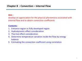
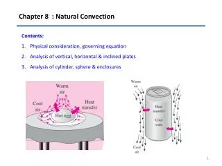
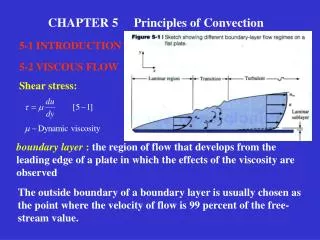
CHAPTER 5 Principles of Convection. 5-1 INTRODUCTION. 5-2 VISCOUS FLOW. Shear stress:. boundary layer : the region of flow that develops from the leading edge of a plate in which the effects of the viscosity are observed.

E N D
CHAPTER 5 Principles of Convection 5-1 INTRODUCTION 5-2 VISCOUS FLOW Shear stress: boundary layer : the region of flow that develops from the leading edge of a plate in which the effects of the viscosity are observed The outside boundary of a boundary layer is usually chosen as the point where the velocity of flow is 99 percent of the free-stream value.
Three regimes of boundary-layer flow 1. Laminar flow 2. Transitional flow 3. Turbulent flow The transition occurs when Renolds number For most analytical purposes, the critical number for the transition is usually taken as
The critical Re for transition is strongly dependent on the surface roughness condition and the “turbulent level”of the free-stream. The normal range for the beginning of transition is between : For very large disturbances present in the flow, transition may begin with Renolds number as low as Foe flows that are very free from fluctuation, the transition may not start until The transition is completed at Re twice the value at the transition begin.
The relative shape for the velocity profiles in laminar and turbulent flow The laminar profile is approximately parabolic Structure of turbulent profile : Laminar sublayer that is nearly linear. Turbulent portion which is relatively flat in comparison with the laminar profile.
The physical mechanism of viscosity in fluids In laminar flow, the viscosity is attributed to the exchange of momentum between different laminas by the movement of molecules. For a gas In turbulent flow, the momentum exchange between different layers is caused by the macroscopic movement of fluid chunks. We can expect a larger viscous-shear in turbulent flow than in laminar flow, due to which the velocity profile is flat in a turbulent boundary layer.
Flow in a tube The critical Re The range of Re for transition is Continuity relation in a tube is Re based on mass velocity is defined as
5-3 INVISCOUS FLOW The Bernoulli equation for flow along a stream results: In differential form, The energy equation for compressible fluid i is the enthalpy defined by
Equation of state of fluid Relations applicable to reversible adiabatic flow:
5-4 LAMINAR BOUNDARY LAYER ON A FLAT PLATE • Assumptions: • Incompressible and steady flow • No pressure variation in the direction perpendicular to the plate. • Constant viscosity • Viscous-shear in y direction is negligible. Two methods to study motion of fluid. 1. Newton’s law of motion 2. Force balance Which applies to a elemental control volume fixed in space. Which applies to a system of constant mass.
Mass continuity equation Mass in the left face is Mass out of the left face is Mass in the bottom face is Mass out of the top face is Mass balance on the element is Mass continuity equation
Derivation of momentum equation Mass in the left face is Momentum flux in the left face is Momentum flux out of the left face is Mass in the bottom face is Momentum flux in the x direction entering the bottom face Mass out of the top face is Momentum flux in the x direction leaving the top face
Pressure forces on the left and right faces are and Net pressure force in the direction of motion is Viscous-shear force on the bottom face is Viscous-shear force on the top face is Balancing force and momentum in x direction gives Final result ——Momentum equation
Integral momentum equation of the boundary layer. Mass flow through plane 1 [a] Momentum flow through plane 1 [b] Momentum flow through plane 2 [c] Mass flow through plane 2 [d] Carried momentum in x direction by the flow through plane A-A The net momentum flow out of the control volume is
By the use of or The pressure force on plane 1 is The pressure force on plane 2 is The shear force at wall is Setting the force on the element equal to the net increase in momentum gives ——Integral momentum equation of the boundary layer.
For constant pressure,from Bernoulli equation One obtains Integral momentum equation of the boundary layer becomes
Evaluation of boundary layer thickness Boundary conditions are Inserting the expression into equation [5-17] For constant-pressure condition Carrying out the integration leads to suppose Appling boundary conditions obtains Separation of variables leads to
, so that In terms of Renolds number Exact solution
5-5 ENERGY EQUATION OF THE BOUNDARY LAYER • Assumptions: • incompressible steady flow • Constant viscosity ,thermal conductivity, and specific heat • Negligible heat conduction in the direction of flow Energy convected in left face + energy convected in bottom face + energy conducted in bottom face +net viscous work done on element = energy convected out right face + energy out top face +heat conducted out top face
The viscous shear force over dx The distance through which the force moves in respect to the control volume dxdy is The net viscous energy delivered to the element is [5-12] Energy balance corresponding to the quantities shown in figure 5-6 is [5-22] Using And dividing by gives ——Energy equation of the laminar boundary layer.
Order-of-magnitude analysis [5-25] [5-23] [5-26] A striking similarity between [5-25] and [5-26] [5-24]
5-6 THE THERMAL BOUNDARY LAYER 1. Thermal boundary layer 2. Definition of h [5-27] [5-28] [5-29] 3. Temperature distribution in the thermal boundary layer Boundary conditions At y=0 [a] [c] At [b] At At y=0 [d]
Conditions (a) to (d) may be fitted to a cubic polynomial [5-30] 4. Integral energy equation of the boundary layer Energy convected in +viscous work within element +heat transfer at wall=energy convected out The energy convected through plane 1 is The energy convected out through plane 2 is The net viscous work done within element is The mass flow through plane A-A Heat transfer at wall The energy carried with is
Combining the above energy quantities gives [5-32] ——integral energy equation of the boundary layer. 5. Thermal boundary layer thickness Inserting (5-30) and (5-19) into (5-32) gives [5-30]
Assume thermal boundary layer is thinner than the hydrodynamic boundary layer Making substitution 5-33 5-34 Neglecting gives Performing the differentiation gives or But according to page 217 and
so that we have 5-35 Noting that Solution is When the boundary condition at at is applied , the final solution become 5-36 where 5-37 When the plate is heated over the entire length 5-38
6. Prandtl number(see page 225) 5-39 7. Nusselt number 5-40 Substituting (5-21) and (5-36) gives 5-41 Nusselt number 5-42 Finally, 5-43 For the plate heated over its entire length 5-44
9. Average heat transfer coefficient and Nusselt number 5-45 or 5-46a 5-46b where Film temperature 5-47
10. Constant heat flux 5-48 5-49 5-50 or 11. Other relations For laminar flow on an isothermal flat plate 5-51 For Rex Pr>100 For the constant-heat-flux case, 0.3387 is changed to 0.4637, and 0.0468 is replaced by 0.0207.
Basic laws for inviscous flow Velocity and temperature distributions Mass continuity equation Results: Momentum equation Integral momentum equation Energy equation A striking similarity Integral energy equation
5-7 THE RELATION BETWEEN FLUID FRICTION AND HEAT TRANSFER [5-52] The shear stress is Using the velocity distribution given by equation(5-19), we have Making use of the relation for the boundary-layer thickness gives Combining (5-52) and (5-53) leads to
The exact solution is [5-44] may be rewritten as By introduction of Stanton number ——Reynolds-Colburn analogy
5-8 TURBULENT-BOUNDARY-LAYER HEAT TRANSFER • Structure of turbulent flow: • Laminar sublayer • Buffer layer • Turbulent The physical mechanism of heat transfer in turbulent flow is similar to that in laminar flow. Difficulty: there is no completely adequate theory to predict turbulent-flow behavior velocity fluctuation in a turbulent flow
Shear stress giving rise to velocity fluctuations in turbulent flow Eddy Viscosity and Mixing Length ( 湍流粘度与混合长度 ) Mean free path and Prandtl mixing length Prandtl postulated:
Nondimensional coordinates Prandtal’s hypothesis In the near-wall region For laminar sublayer Universal velocity profile
For fully turbulent region From equation [5-65], we have Substituting this relation along with equation (5-64) into equation (5-63) gives or Substituting this relation into Eq (5-69) for and integrating gives Universal velocity profile Laminar sublayer : 0<y+<5 Buffer layer : 5<y+<30 Turbulent layer : 30<y+<400 For fully turbulent region For regions where both molecular and turbulent energy transport are important
Turbulent Heat Transfer Based on Fluid-Friction Analogy 1. Fluid-friction analogy 3. Average-friction coefficient for a flat plate: A simpler formula for lower Reynolds number is 2. The local skin-friction coefficient over a flat plate: Table 5-1 4. Local turbulent heat transfer coefficient
5. Average heat transfer coefficient over the entire laminar-turbulent boundary layer For higher Reynolds number,using equation (5-79), one obtains From , the above equation can be rewritten as 6. Equation suggested by Whitaker Alternatively, for the laminar portion for the turbulent portion Constant Heat Flux One obtains
TURBULENT BOUNDARY LAYER THICKNESS 1. Velocity profile in a turbulent boundary layer The first case: The boundary layer is fully turbulent from the leading edge of the plate: 2. Shear stress at wall The second case: The boundary layer follows a laminar growth pattern up to and a turbulent growth thereafter So that 3. Integrating the integral momentum equation Integrating [5-90] leads to Combining the above various relations gives Integrating and clearing terms gives
(a) Semilog scale Boundary-layer thickness for atmospheric air at u=30m/s. (b) log scale
5-10 HEAT TRANSFER IN LAMINAR TUBE FLOW 1. Velocity distribution 5-98
2. Energy balance analysis and temperature distribution Net energy convected out = net heat conducted in which may be rewritten
5-98 assume B.C: Inserting Eq (5-98) into Eq (5-99)
Bulk temperature 4. Convection heat transfer coefficient 1. Definition of convection heat transfer coefficient in tube flow Local heat flux = 2. Bulk temperature ( 整体温度 ) 3. Wall temperature
5-11 TURBULENT FLOW IN A TUBE ( a ) For laminar flow assume Integrating (a) For turbulent flow Heat transfer at wall is
Substituting ( B ) and ( C ) into ( A ) gives ( A ) ( D ) Reynolds analogy for tube flow Heat transfer at wall is ( B ) Shear stress at wall is The pressure drop can be expressed in terms of friction factor ( D ) is modified by Pr So that A more correct relation ( C )