Download
1 / 46
470 likes | 1.02k Views
Common Electrical Hazards in the Workplace Including Arc Flash. Introduction.

E N D
Common Electrical Hazards in the Workplace Including Arc Flash
Introduction This material was produced under grant number SH-16615-07-60-F-12 from the Occupational Safety and Health Administration, U.S. Department of Labor. It does not necessarily reflect the views or policies of the U.S. Department of Labor, nor does mention of trade names, commercial products, or organizations imply endorsement by the U.S. Government. This material was produced by the Workplace Safety Awareness Council, a 501(c)(3) not-for-profit organization dedicated to safety in the workplace. For further information about the council or upcoming safety related training, please visit our website at www.wpsac.orgor call us at (863) 537-4053.
What’s New In February 1972, OSHA incorporated the 1971 edition of the National Fire Protection Association's (NFPA) National Electrical Code (NEC), NFPA 70-1971 On January 16, 1981, OSHA revised its Electrical standard with Part I of National Fire Protection Association's (NFPA) 70E - 1979 On August 13, 2007, OSHA revised its Electrical standard to reference National Fire Protection Association's (NFPA) 70E - 2000
Common Hazards • Common hazards when working with energized electrical equipment include: • Electric Shock / Burns • Blast • Arc Flash Fast Fact: It doesn’t take much for human skin to burn – in fact an exposure of 203 F for just one-tenth of a second (6 cycles) is enough to cause a third degree burn!
GFCI Protection 1910.304(b)(3)(i) Receptacles installed in bathrooms or on rooftops shall have ground-fault circuit-interrupter protection for personnel.
GFCI Protection 1910.304(b)(3)(ii)(A) Receptacle outlets (including cord sets) that are not part of the permanent wiring of the building shall have ground-fault circuit-interrupter protection for personnel.Note: A cord connector on an extension cord set is considered to be a receptacle outlet if the cord set is used for temporary electric power.
Flexible Cords – Permitted Use 1910.305(g)(1)(ii)(A)-(L) • Pendants; • Wiring of fixtures; • Connection of portable lamps or appliances; • Portable and mobile signs; • Elevator cables; • Wiring of cranes and hoists; • Appliances to permit removal for maintenance and repair Portable lamps, tools or appliances Stationary equipment to facilitate interchange Pendant, or Fixture Wiring
Flexible Cords – Permitted Use 1910.305(g)(1)(ii)(A)-(L) • Connection of stationary equipment to facilitate their frequent interchange; • Prevention of the transmission of noise or vibration; • Appliances where the fastening means and mechanical connections are designed to permit removal for maintenance and repair; • Data processing cables approved as a part of the data processing system; • Connection of moving parts; and • Temporary wiring as permitted in paragraph (a)(2) of this section.
Prohibited Uses of Flexible Cords1910.305(g)(1)(iv)(A)-(F) • As a substitute for the fixed wiring of a structure; • Where run through holes in walls, ceilings, or floors; • Where run through doorways, windows, or similar openings; • Where attached to building surfaces; • Where concealed behind building walls, ceilings, or floors; or • Where installed in raceways, except as otherwise permitted in this subpart. Concealed behind or attached to building surfaces Substitute for fixed wiring Run through walls, ceilings, floors, doors, or windows
Flexible Cords 1910.304(b)(3)(ii)(C)(3) • Extension cords must be visually inspected before each use on any shift. Examine the cord for • Missing grounding pin • Damaged other jacket (tear in insulation) • Possible internal damage (pinched cord)
Grounding Pin 1910.304(b)(3)(ii)(C)(4)(i) – (iii) Ensure that grounding pin on extension cords is in place and operable • All equipment grounding conductors shall be tested for continuity: • Before first use • Before return to service (repairs) • Before use after an incident that may have caused damaged and • Intervals not to exceed three (3) months
Splices 1910.305(g)(2)(ii) Flexible cords may be used only in continuous lengths without splice or tap. Note: Black electrical tape does not provide suitable insulation and is not acceptable
Flexible Cords 1910.305(g)(2)(i) • Durably marked as to type, side, and number of conductors • Strain relief must be provided
Wire Gauge WIRE Inadequate Wiring Hazards • Using a portable tool with an extension cord that has a wire too small for the tool: • The tool will draw more current than the cord can handle, causing overheating and a possible fire without tripping the circuit breaker • The circuit breaker could be the right size for the circuit but not for the smaller-wire extension cord Wire gauge measures wires ranging in size from number 36 to 0 American wire gauge (AWG)
Minimum Depth of Working Space1910.303(g)(1)(i)(A) Table S-1 Condition A -- Exposed live parts on one side and no live or grounded parts on the other side Condition B -- Exposed live parts on one side and grounded parts on the other side Condition C -- Exposed live parts on both sides
Labeling of Breakers 1910.303(f)(2) –(3) • Overcurrent devices or disconnecting devices: • shall be legibly marked to indicate its purpose • shall be of sufficient durability to withstand the environment involved.
Cabinets, Boxes and Fittings1910.305(b)(1)(i) • Conductors entering shall be protected • Openings shall be effectively closed • Cable is fastened within 12” from box or raceway
Cabinets, Boxes and Fittings1910.305(b)(1)(i) • Conductors entering shall be protected • Openings shall be effectively closed • Cable is fastened within 12” from box or raceway
Cabinets, Boxes and Fittings1910.305(b)(1)(i) • Conductors entering shall be protected • Openings shall be effectively closed • Cable is fastened within 12” from box or raceway
Cabinets, Boxes and Fittings1910.305(b)(2)(i) In completed installations, each outlet box shall have a cover, faceplate, or fixture canopy.
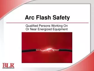
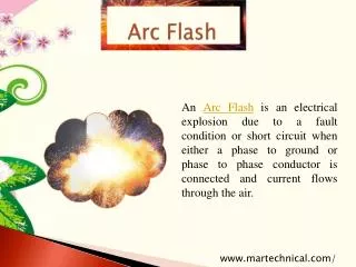
Arc Flash Event • A dangerous release of energy created by an electrical fault • Release will contain: • Thermal energy • Acoustical energy • Pressure wave • Debris
Arc Flash Intensity • Variables that effect the size and energy of an electric arc flash: • Amperage • Voltage • Arc Gap • Closure time • Distance away from arc • 3 phase v single phase • Confined space
Arc Energy Basics • Exposure energy expressed in cal/cm2 • ½ to 1 cal/cm2 = hottest part of lighter in 1 sec • 1-2 calorie exposure will cause second degree burn on human skin • Typical non-FR workwear can ignite @4-5cals • Arcs typically release 5-30 cals - energies of 30-60 cals are not uncommon
Arc Flash Events • Can reach 35,000 F • Fatal burns >10 feet • Majority of hospital admissions are arc flash burns, not shock • 30,000 arcs and 7000 burn injuries per year • Over 2000 people admitted to burn centers yearly with severe arc flash burns
What Is Important • Three factors are critical when discussing burns: • Extent (% of body burned – related to survivability) • Severity (linked to quality of life) • Location (linked to quality of life)
What Is a Burn? • A chemical process which progressively injures skin; severity relates to depth • 1st : redness, pain – not permanent • 2nd: blistering – skin will regenerate • 3rd: total skin depth destroyed. Will not regenerate – requires grafting • 4th : Underlying muscle damaged
Burn Survival • Burn percentage, more than severity, predicts survival because skin is infection barrier • 2nd and 3rd degree break skin, providing an infection pathway • Most hospital deaths 2-4 weeks post-exposure are infection (gram-neg staph)
Burn Survival Factors • Odds of survival fall with total % burn • Odds of survival fall precipitously above 50% burn • Odds of survival fall as age increases
Burn Injury • Burn treatment requires approx. 1.5 days hospitalization per % burn • Average hospitalization is 19 days, at costs exceeding $18,000/day • Total hospitalization cost typically ranges from $200,000 to $750,000, with many over $1,000,000 USD
Deenergized Equipment The most effective and fool-proof way to eliminate the risk of electrical shock or arc flash is to simply deenergize the equipment. . .
Lockout / Tagout A lock and a tag shall be placed on each disconnecting means used to deenergize circuits and equipment on which work is to be performed. Note: Electric equipment that have been deenergized but have not been locked out or tagged shall be treated as energized.
Working Live • OSHA has also made allowances for not deenergizing electrical equipment when it would increase current hazards or create additional hazards, for example: • interruption of life support equipment, • deactivation of emergency alarm systems, • shutdown of hazardous location ventilation equipment, • removal of illumination for an area. • Working live is also allowable due to infeasibility of deenergization (i.e. testing of electric circuits)
Hot Work Requirements • Employer must develop and enforce safety-related work practices to prevent electric shock or other injuries resulting from either direct or indirect electrical contacts. • These safety related work practices could include: • Energized Electrical Work Permit • Pre-work Job Briefing • Personal Protective Equipment • Insulated Tools • Written Safety Program • Qualified Person Training • Flash Hazard Labeling
Definitions A number of “approach boundaries” exist and both qualified and non-qualified persons must understand these definitions.
Flash Protection Boundary Flash Protection Boundary (outer boundary): The flash boundary is the farthest established boundary from the energy source. If an arc flash occurred, this boundary is where an employee would be exposed to a curable second degree burn (1.2 calories/cm2)
Limited Approach Boundary Limited Approach: An approach limit at a distance from an exposed live part where a shock hazard exists. “Working Near Live Parts” Occurs when any activity inside the Limited Approach Boundary is undertaken
Restricted Approach Boundary Restricted Approach: An approach limit at a distance from an exposed live part which there is an increased risk of shock.
Prohibited Approach Boundary Prohibited Approach (inner boundary): A distance from an exposed part which is considered the same as making contact with the live part. “Working On Live Parts” Occurs when coming in contact with live parts, including test equipment, body, PPE, tools etc. . .
Flash Protection Labeling • Arc Flash Hazard labeling must be posted which identifies: • Approach boundaries • PPE required
How to Determine Boundaries NFPA Tables: Refer to NFPA 70E – 2000 Table 3-3.9.1 or Table 130.7(C)99)(a) NFPA 70E – 2004. Pro: Easiest and quickest method Con: Provides the least amount of accuracy. Limited tasks are covered in tables
How to Determine Boundaries Formula Method: NFPA 70 E and IEEE Standard 1584 provides formulas that can be used to accurately determine the approach boundaries. Pro: More accurate and all inclusive than NFPA tables Con: Is time consuming, requires an engineer level of expertise and is subject to human error.
How to Determine Boundaries Approach Calculator: IEEE and others have provided a spreadsheet based calculator to assist in determining approach boundaries. Pro: Quicker than formula method Con: Still requires detailed information about the equipment and circuit often requiring the use of an electrical engineer.
How to Determine Boundaries Software: There exists on the market various software products that can simplify and expedite the approach boundary calculations. Pro: Creates one-line diagrams and arc flash labels based on data entered Con: Cost and equipment / circuit knowledge is still required often requiring an engineer.
Qualified Persons Qualified person: One who has received training in and has demonstrated skills and knowledge in the construction and operation of electric equipment and installations and the hazards involved.
Qualified Person Training1910.332(b)(3)(i) – (iii) • Qualified persons shall at a minimum be trained in the following areas: • The skills to distinguish exposed live parts from other parts of electric equipment. • The skills to determine the nominal voltage of exposed live parts, and • The clearance distances specified in 1910.333(c) and the corresponding voltages to which the qualified person will be exposed.