Download
1 / 40
430 likes | 939 Views
Lecture 11 - User Interface Design and Component Level Design. The Golden Rules User Interface Design Task Analysis and Modeling Interface Design Activities Implementation Tools Design Evaluation Structured Programming Comparision of Design. Overview.

E N D
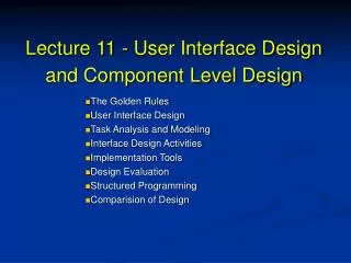
Lecture 11 - User Interface Designand Component Level Design The Golden Rules User Interface Design Task Analysis and Modeling Interface Design Activities Implementation Tools Design Evaluation Structured Programming Comparision of Design
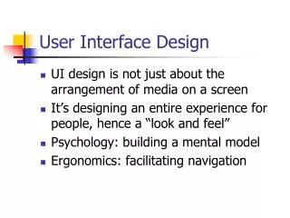
Overview Proper interface design begins with careful analysis of the user, the task and the environment. Once the user's tasks are identified, user scenarios are created and validated. Good user interfaces are designed, they don't happen by chance. Prototyping is a common approach to user interface design. Early involvement of the user in the design process makes him or her more likely to accept the final product. User interfaces must be field tested and validated prior to general release.
Easy to learn? Easy to use? Easy to understand?
Typical Design Errors lack of consistency too much memorization no guidance / help no context sensitivity poor response Arcane/unfriendly
The Golden Rules 1、Place the user in control 2、Reduce the user’s memory load 3、Make the interface consistent
Place User in Control • Define interaction in such a way that the user is not forced into performing unnecessary or undesired actions • Provide for flexible interaction (users have varying preferences) • Allow user interaction to be interruptible and reversible
Streamline interaction as skill level increases and allow customization of interaction • Hide technical internals from the casual user • Design for direct interaction with objects that appear on the screen
Reduce User Memory Load • Reduce demands on user's short-term memory • Establish meaningful defaults • Define intuitive short-cuts • Visual layout of user interface should be based on a familiar real world metaphor • Disclose information in a progressive fashion
Make Interface Consistent • Allow user to put the current task into a meaningful context • Maintain consistency across a family of applications • If past interaction models have created user expectations, do not make changes unless there is a good reason to do so
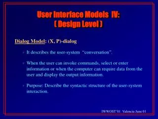
User Interface Design Models • Design model (incorporates data, architectural, interface, and procedural representations of the software) • User model (end user profiles - novice, knowledgeable intermittent user, knowledgeable frequent users) • User's model or system perception (user's mental image of system) • System image (look and feel of the interface and supporting media)
User Interface Design Process • User, task, and environment analysis and modeling • Interface design • Interface construction • Interface validation
Task Analysis and Modeling • Software engineer studies tasks human users must complete to accomplish their goal in the real world without the computer and map these into a similar set of tasks that are to be implemented in the context of the user interface
Software engineer studies existing specification for computer-based solution and derives a set of tasks that will accommodate the user model, design model, and system perception • Software engineer may devise an object-oriented approach by observing the objects and actions the user makes use of in the real world and model the interface objects after their real world counterparts
Interface Design Activities • Establish the goals and intentions of each task • Map each goal/intention to a sequence of specific actions (objects and methods for manipulating objects) • Specify the action sequence of tasks and subtasks (user scenario)
Indicate the state of the system at the time the user scenario is performed • Define control mechanisms • Show how control mechanisms affect the state of the system • Indicate how the user interprets the state of the system from information provided through the interface
Interface Design Issues • System response time (time between the point at which user initiates some control action and the time when the system responds) • User help facilities (integrated, context sensitive help versus add-on help)
Error information handling (messages should be non-judgmental, describe problem precisely, and suggest valid solutions) • Command labeling (based on user vocabulary, simple grammar, and have consistent rules for abbreviation)
User Interface Evaluation Cycle • Preliminary design • Build first interface prototype • User evaluates interface • Evaluation studied by designer • Design modifications made • Build next prototype 7. If interface is not complete then go to step 3
preliminary design build prototype #1 interface build prototype # n interface user evaluate's interface design modifications are made evaluation is studied by designer Interface design is complete Design Evaluation Cycle
User Interface Design Evaluation Criteria • Length and complexity of written interface specification provide an indication of amount of learning required by system users • Number of user tasks and the average number of actions per task provide an indication of interaction time and overall system efficiency
Number of tasks, actions, and system states in the design model provide an indication of the memory load required of system users • Interface style, help facilities, and error handling protocols provide a general indication of system complexity and the degree of acceptance by the users
Component Level Design The purpose of component level design is to translate the design model into operational software. Component level design occurs after the data, architectural, and interface designs are established. Component-level design represents the software in a way that allows the designer to review it for correctness and consistency, before it is built. The work product produced is the procedural design for each software component, represented using graphical, tabular, or text-based notation.
What is a Component? • OMG Unified Modeling Language Specification [OMG01] defines a component as • “… a modular, deployable, and replaceable part of a system that encapsulates implementation and exposes a set of interfaces.” • OO view: a component contains a set of collaborating classes • Conventional view: logic, the internal data structures that are required to implement the processing logic, and an interface that enables the component to be invoked and data to be passed to it.
analysis class Print Job numberOfPages numberOf Sides paperType magnification productionFeatures design component computeJob computeJobCost( ) passJobtoPrinter( ) PrintJob initiateJob number Of Pages elaborated design class number Of Sides paper Type <<interface>> PrintJob paper Weirht computeJob paper Size computePageCost( ) paper Color computePaperCost( ) magnification computeProdCost( ) color Requirement computeTotalJobCost( ) production Features collationOptions bindingOptions coverStock bleed priority totalJobCost WOnumber <<interface>> computePageCost( ) computePaperCost( ) initiateJob computeProdCost( ) computeTotalJobCost( ) buildWorkOrder( ) buildWorkOrder( ) checkPriority( ) checkPriority( ) passJobtoProduction( ) passJobtoProduction( ) OO Component
Basic Design Principles • The Open-Closed Principle (OCP).“A module [component] should be open for extension but closed for modification. • The Liskov Substitution Principle (LSP).“Subclasses should be substitutable for their base classes. • Dependency Inversion Principle (DIP).“Depend on abstractions. Do not depend on concretions.” • The Interface Segregation Principle (ISP). “Many client-specific interfaces are better than one general purpose interface. • The Release Reuse Equivalency Principle (REP).“The granule of reuse is the granule of release.” • The Common Closure Principle (CCP).“Classes that change together belong together.” • The Common Reuse Principle (CRP).“Classes that aren’t reused together should not be grouped together.”
Design Guidelines • Components • Naming conventions should be established for components that are specified as part of the architectural model and then refined and elaborated as part of the component-level model • Interfaces • Interfaces provide important information about communication and collaboration (as well as helping us to achieve the OPC) • Dependencies and Inheritance • it is a good idea to model dependencies from left to right and inheritance from bottom (derived classes) to top (base classes).
Design Guidelines • Components • Naming conventions should be established for components that are specified as part of the architectural model and then refined and elaborated as part of the component-level model • Interfaces • Interfaces provide important information about communication and collaboration (as well as helping us to achieve the OPC) • Dependencies and Inheritance • it is a good idea to model dependencies from left to right and inheritance from bottom (derived classes) to top (base classes).
Algorithm Design • the closest design activity to coding • the approach: • review the design description for the component • use stepwise refinement to develop algorithm • use structured programming to implement procedural logic • use ‘formal methods’ to prove logic
open walk to door; reach for knob; repeat until door opens open door; turn knob clockwise; if knob doesn't turn, then walk through; close door. take key out; find correct key; insert in lock; endif pull/push door move out of way; end repeat Stepwise Refinement
Structured Programming • Each block of code has a single entry at the top • Each block of code has a single exit at the bottom • Only three control structures are required: sequence, condition (if-then-else), and repetition (looping) • Reduces program complexity by enhancing readability, testability, and maintainability
Design Notation • Flowcharts (arrows for flow of control, diamonds for decisions, rectangles for processes) • Box diagrams (also known as Nassi-Scheidnerman charts - process boxes subdivided to show conditional and repetitive steps)
Decision table (subsets of system conditions and actions are associated with each other to define the rules for processing inputs and events) • Program Design Language (PDL - structured English or pseudocode used to describe processing details)
add a condition Z, if true, exit the program a x 1 b c x 2 d x 3 f e x 4 g x 5 Flowchart constracts
Conditions 1 2 3 4 5 6 Regular customer T T Silver customer T T Gold customer T T Special discount F T F T F T Actions No discount Apply 8 percent discount Apply 15 percent discount Apply additional percent discount Decision Table Rules
Program Design Language (PDL) if condition x T F then process a; X a else process b; b endif if-then-else PDL easy to combine with source code machine readable, no need for graphics input graphics can be generated from PDL enables declaration of data as well as procedure easier to maintain
Program Design Language Characteristics • Fixed syntax with keywords providing for representation of all structured constructs, data declarations, and module definitions • Free syntax of natural language for describing processing features • Data declaration facilities for simple and complex data structures • Subprogram definition and invocation facilities
Design Notation Assessment Criteria • Modularity (notation supports development of modular software) • Overall simplicity (easy to learn, easy to use, easy to write) • Ease of editing (easy to modify design representation when changes are necessary) • Machine readability (notation can be input directly into a computer-based development system) • Maintainability (maintenance of the configuration usually involves maintenance of the procedural design representation)
Structure enforcement (enforces the use of structured programming constructs) • Automatic processing (allows the designer to verify the correctness and quality of the design) • Data representation (ability to represent local and global data directly) • Logic verification (automatic logic verification improves testing adequacy) • Easily converted to program source code (makes code generation quicker)