Download
1 / 62
620 likes | 788 Views
Geotechnical properties and stress-strain-time behavior evaluation of industrial waste deposits in Bulgaria. by Prof. D-r Eng. Trifon Germanov Department of Geotechnics.

E N D
Geotechnical properties and stress-strain-time behavior evaluation of industrial waste deposits in Bulgaria by Prof. D-r Eng. Trifon Germanov Department of Geotechnics
This report presents the results from some recent studies elaborated under supervision of the author. Part of the results under consideration are reported on theMain Session 1 - “Man Made deposits - recent and ancient” of the13th European Conference on Soil Mechanics and Geotechnical Engineering, Prague, 2003. • The results presented in this report are published in the Proceedings of the Conference as followed: • Germanov, T. (2003).“Geotechnical properties of industrial waste deposits in Bulgaria”. Proceeding XIIIth European conference on SMGE, Prague, Vol.1, pp. 93-101. • Germanov, T. (2003). “Limit states (Stability, deformation, erosion….)”. Proceeding XIIIth European conference on SMGE, Prague, Vol.3, pp. 119 - 125.
Basic consideration • The stability of waste deposits, such as tailings dam, landfill, waste banks and other depends on the mechanical properties of the waste materials and the shape of the deposit’s body. • The basic principles of soil mechanics are usually used for the purpose. On the other hand, the materials included in the waste deposits often have an unusual behavior, different from natural soils. • This circumstancerequires a comprehensive program for laboratory and in situ study for determination of the real mechanical properties of the waste materials • Summarizing the problems, related to the stability of waste deposits, the following limit states could be considered: • slope stability analysis, • bearing capacity, • subgrade settlement and differential surface settlement, • erosion (internal and surface).
Basic consideration • The slope stabilityanalysisis very important problem, mainly for the tailings dams and landfills, where a slope failure under gravity and filtration efforts is possible. Depending on the type of the project, different design methods are used. If the type of the slip surface is accepted, conventional (based on the Bishop, Jnbu or Spencer principles) methods could be applied. • Erosionis important problem in the case of tailings, ash or other dams built up of fine-grained materials where, after raining, a surface slope failure is possible. • The most parts of the industrial waste deposits are in water-saturated conditions. By this reason, the effect of thepore water pressureshould be taken into account evaluating the deposit stability.
Part 1. Geotechnical Properties of some industrial waste deposits in Bulgaria
Introduction • The design of geotechnical works related to encapsulation and stability analysis of industrial waste deposits requires the determination of real physical and mechanical properties of the waste material. • The Soil Mechanics principles are usually used for this purpose. • However, taking into account the specific features of the waste materials (short time of deposit, usually uniformly grain size distribution, great ability for deformation), some deviations from the standard methods for soils testing are possible. • During the last 10-15 years an intensive program for construction works related to the environmental protection in Bulgaria has started.
Introduction • Part of this program is related to designing of equipment with the purpose to encapsulation and remediation of industrial waste deposits. • The laboratory of Soil and Rock Mechanics at the University of Architecture, Civil Engineering and Geodesy took part in these programs, mainly conducting laboratory testing for determination of geotechnical properties of waste materials.
Introduction • Only part of the results from laboratory testing is presented in the here. • Three projects, developed under supervision of the author are considered: • Encapsulation of “Blue lagoon”; • Encapsulation of the oxidative pond near the town of Burgas; • Stability analysis of “Liuliakovitsa” tailings dam. • The waste deposits, under consideration, are situated in different part in Bulgaria.
Encapsulation of “Blue Lagoon” • The slime pond (called “Blue Lagoon”) is situated on the territory of the Pirdop Copper Metallurgical Plant located some 70 km to the east of Sofia. Industrial activities on this site started in the late 1950’s. • The Blue Lagoon designates the settling pond, which contains the calcium arsenic precipitate (slime) coming from the copper metallurgical plant. • The northern edge of the Blue Lagoon is rather close to the Sofia-Burgas railway. • The initial slime pond was constructed in 1956, mostly on the original sloping (~ 3.5%) ground surface of alluvial soil with a high clay content which is underlain by gneiss bedrock. • The elevation of the bedrock surface is variable.
Encapsulation of “Blue Lagoon” • Drill holes advanced to either establish the depth to be more than 20 m below the ground surface. • The slime surface has an area of about 9.6 ha and the greatest depth, in 1997 was 12.70 m below the slime surface. • The estimated total volume of the stored sediments (slime) was about 600 000 m3.
Encapsulation of the oxidative pond near Burgas • The oxidative pond is situated near the quarter “Meden Rudnik” (Cooper mine) in the town of Burgas. • To the west the pond is bounded by “Mandra” dam. At first, the pond had been used as a settling basin for water supply. • During 1984 it was taken out from the scheme of the water treatment and had been used as a site for deposit of floating refuse products from cleaning of the other oxidative ponds. • During 1991 the free filling of the pond by mixture of constructions refuses, sediments and ash from the ovens for burning of petroleum and biological sediments began. As a result of this, an area of 298 ha was filled. • Thus, the oxidative pond was formed of three parts: filled body (swamp), settled lake, and slime field.
“Liuliakovitsa” tailings dam stability analysis • The tailings dam “Liuliakovitsa” is a part of the Assarel cooper flotation plant, designed with an improved construction. • Its final height will be 190 m. The starter dam, built of draining rock fill, has a tongue-shaped projecting lower upstream part. The length of this part is equal to the distance from the starter dam to the decant pond at the initial stage. It is calculated to ensure stability of the tailings dam at its final height. • The coarser fractions are laid off in the supporting part over the tongue, and the finer material is washed off into the pond. • This kind of sorting makes it possible to use the good strength of the coarse tailings deposited over the tong, as a substitute of the rockfill.
“Liuliakovitsa” tailings dam stability analysis • The construction of the starter dam began late in 1984, and the deposition of the tailings started in 1990. • Preliminary study for determination of consolidation characteristics of the tailings, obtained in laboratory, was carried out in 1987. • Nowadays, the height of tailings dam reaches to 130 m • Thus, supporting starter dam of rockfill with a lower-than-usual height is used.
Methodology of the laboratory testing • Waste materials sampling • The aim of sampling is to obtain samples for identification of the waste materials as well as to perform laboratory testing for determination of the geotechnical properties. • The techniques used for sampling depend on the in-situ conditions of the settled waste materials. • Different methods for sampling are applied. • The drilling works in the Blue Lagoonwere done according to preliminary elaborated pattern of borehole net, consisting of 32 drillings, with dimensions of gird 50m to 50 m. • A floating caisson/pontoon was used. • Sampling was done through an opening in the center of the pontoon by means of a pipe-drilling device of 2.5 inches, internal diameter, with jointed sections of 100 cm each.
Waste materials sampling • During the process a total of 220 m have been drilled and 225 samples were taken. • The samples for laboratory study were delivered in liquid condition using plastic bottles. • Before the beginning of the official program of laboratory geotechnical study, several methodological compression tests were carried out. • A similar methodologyhas been applied for sampling of the refuse materials from the oxidative pond.
Preliminary methodological compression tests of the slime from “Blue Lagoon” • Two bottles with slime, taken from 0,5m and 4,5m depth were used for the purpose. Both samples have approximately uniform initial density and water content. • The following initial characteristics for the sample from 4,5m depth are determined: • water content Wn0=205,6%; • wet density rn0=1,185 g/cm3; • dry density rd0=0,397 g/cm3; • void ratio e0=5,73; • degree of saturation Sr =1,00.
Initial identification characteristics of the refused materials form the oxidative pond • The refuse materials have a large quantity of petroleum products. • To decrease the effect of these products on the geotechnical properties, a special procedure was applied. • At first, the refuse materials have been laid on a filter paper and rest one day to free drying. • After drying in the oven at a temperature of 50 - 60 С0 and after free settling, the refuse materials showed approximately 70% soil particles and 30% organiccontents.
Initial identification characteristics of the refused materials form the oxidative pond • The identification geotechnical characteristics in “natural conditions” are evaluated according to standard methods as follows: • the bulk density in by means of direct filling of the refuse materials in the oedometers; the water content - drying the samples at a temperature of 50 - 60 С0; • grain size distribution – by sieve and areometric analysis. • The average characteristics are given in Table 1.
Basic physical characteristics of the refuse materials from the oxidative pond
Determination of the mechanical properties • Oedometric tests • Two types of oedometer have been used for compression tests: • Oedometer without friction along the circular area of the sample for long term consolidation tests with one side vertical drainage. • ELE Rowe type consolidation cells for compression tests with radial inwards drainage • The oedometric tests of the tailings were carried out directly by using undisturbed samples.
Oedometric tests - “Blue Lagoon” • Taking into account that it is impossible to take undisturbed samples of the slime and refused material from pond “Blue Lagoon” and “Oxidative pond” and after the conclusion that there is not great variation of the unit weight with depth, a non-standard procedure was applied for preparation of samples for all oedometric tests. • According to the approximate evaluation of density of samples, measuring the cell volume, the required mass of the natural slime and refused materials (mixture from 3-4 bottles) was measured. • This mass is put into the cell, compacted uniformly, on 4 - 6 layers
Oedometric tests - results • Time - deformation properties are determined by using time-deformation curves in “log scale” mainly. The coefficients of consolidation Cv are computed applying Casagrande’s method. • The creep indexes Cae (coefficients of secondary consolidation) are computed by using formula: • Cae = (1 + e0)ea,where:e0-initial void ration;ea - coefficient of secondary compression. • Initial times of creeping, t0, are computed from the log-time-settlement curves. • The coefficients of radial consolidation Cri are computed by using square-root time curves according to BS 1377. • The average compression and consolidation characteristics are presented in Table 3.
Triaxial tests - results • Triaxial shear tests were carried out only with slimes and tailings samples. • The following types of triaxial shear tests are performed: undrained-unconsolidated (UU) and consolidated undrained (CU) tests, with pore pressure measurement. • After preparation of the specimen, each triaxial shear test is carried out following the standard procedures according to standards (ASTM D 280-95 and NF P 94-070, October 1994). Each shear strength parameter is determined using four Mohr circles. • The results from UU and CU tests are presented by following relationships: deviator stress-axial strain, pore pressure increment – axial strain and relations t = f(s) and t’ = f(s’) [t’=(s1-s3)/2; s=(s1+s3)/2; s’=(s'1+s'3)/2].Average results from triaxial shear tests are presented in Table 3.
The effect of the pore water pressure on the stress-strain behavior
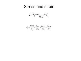
Basic constitutive equations for the pore water pressure evaluation • Following Germanov (2000), the massifs of saturated waste materials could be considered as multi-phase medium and their stress-strain behavior being accompanied by two simultaneous, rheological processes: filtration and creeping. • It is assumed that the deformation of the soil skeleton could be presented according to the theory of linear creep by the equation: where: e0 and e(t) are the initial and variable over time void ratios; q (t) is the sum of normal effective stresses at a fixed point of the soil massifs; K0 is the coefficient of the lateral pressure at rest; mv(t,t ) is the generalized coefficient of volume strain.
Basic constitutive equations for the pore water pressure evaluation m0(t )is the coefficient of instantaneous strain (linear compressibility); j(t )is the function of ageing (tixotropic strengthening) of the soil skeleton. ml is the coefficient of volume creep strain (secondary compression); h - the parameter of creeping speed; mh - the coefficient of "ageing" strain of the soil skeleton; t1 - the parameter of the soil skeleton age (the previous stressed condition). The methods for determining the coefficients of volume strains and the creep parameters are developed by theauthor (see Germanov 2000).
Basic constitutive equations for the pore water pressure evaluation • Assuming that the fluid filtration is according to Darcy's law, the function uw(t,x,y) for two-dimensional consolidation, is determined by the solution of the following differential equation: where: q1(t) = sy(t) + sz(t); sy(t)andsz(t)are the total normal stresses which would be accepted: constant, when the period of operation is considered; variation with a constant velocity for the construction period; variation under cyclic loads (machine foundations or earthquake motions).
Basic constitutive equations for the pore water pressure evaluation • The other coefficients and functions depend on the soil properties. • The author has received an exact solution of the one-dimensional consolidation, under corresponding initials and boundaries conditions, according to equation (Germanov, 1988). Using the finite element method, the two-dimensional consolidation has been solved (Germanov, 2000).
Liquefaction potential evaluation of a tailings dam • The increasing of the pore water pressure under static and dynamic (seismic) excitation loads may lead to decrease the effective stresses to zero. • This phenomenon, known as liquefaction, may provoke a loss of the bearing capacity and failure of the soil massifs. • Evaluation of the exceed pore water pressure under static loading is performed by using the solutions developed by the author (Germanov, 2000), based on the theory of the two-dimensional consolidation, taking into account the rheological properties of the materials.
Liquefaction potential evaluation of a tailings dam • Liquefaction is a phenomenon in which the strength and stiffness of a soil is reduced by earthquake shaking or other rapid loading. • The phenomenon is only generally considered for sandy soils and usually for loose sands. • However, the increase of the pore pressure could reduce the effective pressure, not only in fine-grained soils and coarse-grained soils. • It was established that clay or silt with low plasticity index, such as tailings material, has been found to be as vulnerable to liquefaction (Ishihara, 1985). • One of the criteria for liquefaction potential evaluation is the grain size distribution. • The results of the laboratory investigation of the tailings materials from “Liuliakowitsa” tailings dam shows that the investigatedtailings could be classified as fine silty sand.
The representative grain-size distribution curves are shown below. It can be seen that the grain size curves belong to the boundaries of the most liquefable soils (Ishihara, 1985).This means that in some conditions, tailings could reach to a state of liquefaction.
Liquefaction potential evaluation of a tailings dam • An approximate method based on theoretical evaluation of the increase of pore water pressure in tailings dam’s body during an earthquake is applied herein. • Following Martin & Seed (1978), the basic assumption for pore pressure generation and dissipation analysis is that the excess pore water pressure, uw, in a soil element, could be presented as the sum of the pore water pressure under static loading, uw,st, and pore water pressure increment generated under dynamic excitation - uw,d. • The static pore water pressure uw,st could be computed by using a computer program, developed by the author (Germanov, 2000) based on the constitutive equations given in the paper.
The computations are performed, applying nonlinear experimental relations of the physical and consolidation characteristics and expressing their variation with the dam height. • A cross section of the tailings dam and in situ measured pore water pressure are presented below (Kalchev, 2003). • The computations for static conditions show that there are no differences between theoretical and in-situ measured values of the pore water pressure.
Nonlinear linear characteristics of tailings dam for static analysis
Liquefaction potential evaluation of a tailings dam • The dynamic pore water pressure (uw,d) is computed, considering the tailings dam, under cycling loading, in undrained conditions, by using the expression (Martin & Seed 1978): where:s'0is the effective overburden pressure;N– the number of uniform stress cycles undergone by the soil element;Nl– the number of cycles at the same levels required to reach initial liquefaction.
The number of cycles are accepted: N= 12 for an earthquake with magnitude equal to 7; Nl =50, according to Germanov & Kostov (1994). The distribution of the pore water pressure at the dam height is presented below. The maximum value of pore pressure ratio uw/s'0 reaches to 0.8. It is obviously, under the stress strain conditions, thatthere is no area in tailings dam, which would be susceptible to liquefaction. Liquefactionpotential evaluation of a tailings dam uw,st uw,d
Evaluation of the ultimate stress-strain state of the slime pond before encapsulation
Evaluation of the ultimate stress strain state of the slime pond during encapsulation • One of the variants of the project for encapsulation of the slime pond “Blue Lagoon” considers establishment of drainage wells and filling the pond with granular materials as well as construction of embankment 8 m high. • Another variant without vertical drainage is considered as well. It is supposed that after dewatering the filling will be made approximate by constant speed. • For evaluation of ultimate stress-strain state the Mohr-Coulomb equation for ultimate equilibrium could be used (Germanov, 1986, 2000). • Considering the slime pond in unconsolidated conditions under embankment’s loads, the dimensions of the so-called "plastic zones" could be evaluated by using the expression:
Evaluation of the ultimate stress strain state of the slime pond during encapsulation where,sz, syandtzy, are effective normal and tangential stresses in a given point of the slime pond. The zones of ultimate equilibrium are defined by the conditionqcr >j'(j'- effective angle of internal friction). If these zones are relatively large, the subgrade (slime pond) will lost its overall stability. A computer program for ultimate stress-strain behavior evaluation of saturated soil massifs, taking into account of the pore water pressure generation and dissipation during construction and operation has been developed by the author (Germanov, 1986).
Evaluation of the ultimate stress strain state of the slime pond during encapsulation • Some results from computations are given in Table 4. Two loading steps are considered: q=80 kPa and q=160kPa, corresponding to 4.0 m and 8.0 m embankment fill respectively. All computations are performed by using input data (geotechnical characteristics), according to Germanov (2003). Table 4. qcrvalues for different depts. For this case (j' = 180),the plastic zone could be formed to 6.0m depth at the final stage of loading.
Determination of the time-depending settlement of the Oxidative pond
Determination of the time-depending settlement of the Oxidative pond • The first stage of the project for encapsulation and remediation of the oxidative pond near the town of Burgas, proposes a filling the pond by granular material over geotextile. • The results of the consolidation tests (Germanov, 2003) show some specific features of the petroleum refuses which considerably distinguish them from natural soils. • First of all, the test results show a very low value of densities and very large porosity (rn 1.0 g/cm3; e = 8.0 10.0). • Water content reaches 500 – 600%. • On the other hand, during the consolidation tests, the settlements are developing very slowly over time under small loading. • The great part of the secondary consolidation presumes the presence of rheological processes.
Determination of the time-depending settlement of the Oxidative pond • In order то receive a preliminary prognosis of time-depending settlement, a computation was performed for the subgrade (i.e. petroleum refuses) under loading from embankment 2.0m high. • It is accepted that the construction works (time of filling) will last six months. • The degree of consolidation at the end of construction period and during “operation” after one, two and five years is computed.
Time-depending settlement of the Oxidative pond Table 5. Final settlement and degree of consolidation