Download
1 / 23
240 likes | 392 Views
FPGA based feedback systems used in Synchrotron Light Sources. Guenther Rehm Head of Diagnostics Group Diamond Light Soure. Outline. What is a Synchrotron Light Source? Global Fast Orbit Feedback Bunch-by-Bunch Feedback.

E N D
FPGA based feedback systemsused in Synchrotron Light Sources Guenther Rehm Head of Diagnostics Group Diamond Light Soure FPGA based Feedbacks used in Synchrotron Light Sources
Outline • What is a Synchrotron Light Source? • Global Fast Orbit Feedback • Bunch-by-Bunch Feedback FPGA based Feedbacks used in Synchrotron Light Sources
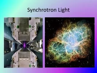
Synchrotron Light (or Radiation) is electromagnetic radiation emitted when a high energy beam of charged particles (electrons) is deflected by a magnetic field How Is Synchrotron Light Produced? a single bending magnet produces a wide fan of radiation multiple bends in an "undulator" or "wiggler" magnet give higher intensity and more directed radiation FPGA based Feedbacks used in Synchrotron Light Sources
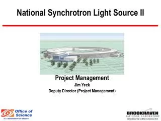
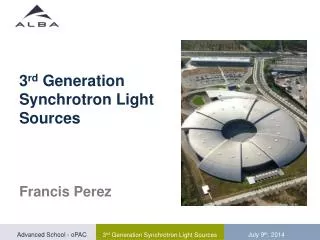
Layout of a 3G Light Source A beam of electrons is accelerated in a LINAC, further accelerated in a booster synchrotron, then accumulated in a storage ring. The circulating electrons emit intense beams of synchrotron light that are sent along beamlines to the experimental stations. FPGA based Feedbacks used in Synchrotron Light Sources
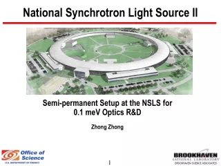
Storage Ring assembled in Tunnel FPGA based Feedbacks used in Synchrotron Light Sources
Typical Operation Parameters of a Synchrotron Light Source FPGA based Feedbacks used in Synchrotron Light Sources
Orbit Stability Requirements in 3rd Generation Light Sources Stability should be better than 10% of the beam dimensions For Diamond nominal optics (at short straight sections) FPGA based Feedbacks used in Synchrotron Light Sources
How can we measure an electron beam position? X~(B+C)-(A+D) Y~(A+B)-(C+D) FPGA based Feedbacks used in Synchrotron Light Sources
Crossbar Switch A/D FPGA A/D A/D A/D Multiplexing in BPM Electronics • Crossbar switch routes all four inputs through all processing channels in parallel, but permutes routing • After digitisation, but before further filtering, the permutation is reversed • By averaging over 4 permutations, any differences/drifts between the channels will be removed (each input will have been routed through each channel during the averaging period) • By examining the changes in the outputs during permutation, the gains of the individual channels can be retrieved and then digitally equalised to reduce artefacts of switching FPGA based Feedbacks used in Synchrotron Light Sources
Fast Orbit Feedback Controls Network Event Network PS VME crate Diagnostics VME crate PMC Rocket IO FB Processor PSU IF PSU IF Processor Processor Event Rx … PSU 1 PSU 14 14 Corrector PSUs eBPM eBPM eBPM eBPM eBPM eBPM eBPM Cell -n Cell +n Cell +m Cell -m FPGA based Feedbacks used in Synchrotron Light Sources
Communication Controller • Within each timeframe (100us), all data received on any input is forwarded once on all outputs FPGA based Feedbacks used in Synchrotron Light Sources
Global Connections of FOFB FPGA based Feedbacks used in Synchrotron Light Sources
FOFB Latencies • Group delay of FIR: 148 µs • Group delay of 2 IIR: 71 µs • Distribution of data around ring: 50 µs • DMA transfer to CPU: 49 µs • Conversion integer to float : 5 µs • Matrix multiplication 2*7*168: 4 µs • PID controller: 1 µs • Write into power supply: 3 µs • Total digital: 331 µs • Total round trip measured 800 µs • Thus: Supply/Magnet/Chamber 470 µs calculated measured FPGA based Feedbacks used in Synchrotron Light Sources
FOFB Performance 60mA Suppression of beam motion FPGA based Feedbacks used in Synchrotron Light Sources
Summary of FPGA tasks for position measurements and orbit feedback • ADC interface • Sample clock PLL to external reference • Channel permutation and equalisation • Digital down conversion / filtering (3 stages) • RAM circular buffer interface • Interface to single board computer • Beam position interlock for machine protection • Communication Controller • Computation of corrector values and PID • Interface to power supplies FPGA based Feedbacks used in Synchrotron Light Sources
Transverse Bunch-by-Bunch Feedback Control System 500 MHz RF clock History buffer 4 AD converters (slicing) RF Frontend 4-way Splitter D igital Signal D A Amplifier Processing Converter FPGA based Feedback Processor Stripline Kicker Button Pickup Corrective kicks applied to individual bunches precisely after a 8-9 turns FPGA based Feedbacks used in Synchrotron Light Sources
A D A D A D A D D A Block Diagram of Libera B-b-B 128M samples buffer (DDR RAM) FIR + 4096 samples buffer (block RAM) Δt=0ns FIR + 250 MHz input output DeMux 4096 samples buffer (block RAM) Δt=2ns DDR FIR + 4096 samples buffer (block RAM) Δt=4ns FIR + 4096 samples buffer (block RAM) Δt=6ns 500MHz f/4 Δt Excitation Generator FPGA 125MHz ADC and FPGA clock FPGA based Feedbacks used in Synchrotron Light Sources
a0 a0 a0 a0 + + + + a1 a1 a1 a1 234 FIFO 234 FIFO 234 FIFO 234 FIFO + + + + a2 a2 a2 a2 234 FIFO 234 FIFO 234 FIFO 234 FIFO + + + + a3 a3 a3 a3 234 FIFO 234 FIFO 234 FIFO 234 FIFO + + + + a4 a4 a4 a4 234 FIFO 234 FIFO 234 FIFO 234 FIFO + + + + a5 a5 a5 a5 234 FIFO 234 FIFO 234 FIFO 234 FIFO + + + + a6 a6 a6 a6 234 FIFO 234 FIFO 234 FIFO 234 FIFO + + + + a7 a7 a7 a7 adjustable FIFO adjustable FIFO adjustable FIFO adjustable FIFO 234 FIFO 234 FIFO 234 FIFO 234 FIFO + + + + FIR Implementation 1,5,9… 2,6,10… sample number 3,7,11… • Each FIR acts on samples from the same bunch after each turn • For this implementation, number of bunches needs to be multiple of 4 4,8,12… FPGA based Feedbacks used in Synchrotron Light Sources
Grow/Damp Measurement • Excite mode for a brief period • switch off excitation, close loop • record mode amplitude, fit decay • repeat for modes FPGA based Feedbacks used in Synchrotron Light Sources
Damping time per mode FPGA based Feedbacks used in Synchrotron Light Sources
Bunch-by-Bunch Feedback in Action • Beam artificially made unstable in both planes: • no feedback • → horizontally unstable • feedback in horiz. plane only • → vertically unstable • feedback in both planes • → stable in both planes FPGA based Feedbacks used in Synchrotron Light Sources
Summary • FPGAs are regularly used in various beam feedback applications in Light Sources • Fast signal processing and huge parallelism can easily be coped with • Systems run perfectly reliable and provide potential for performance improvements or additional features FPGA based Feedbacks used in Synchrotron Light Sources
Thank you for your attention! FPGA based Feedbacks used in Synchrotron Light Sources