Download
1 / 19
190 likes | 289 Views
Explore applications of a versatile carrier board and timer module in FEL systems presented by Richard K. Evans, R. Evans, A. Grippo, and K. Jordan at the Thomas Jefferson National Accelerator Facility. Learn about the design, functions, and future prospects of these modular units, supported by various agencies. Discover how these modules streamline instrumentation, controls, and system integrations for efficient operations. Explore detailed schematics and applications for drive laser pulse control and multipass BPM timing. Join the quest for standardized, adaptable modules enhancing FEL operations.

E N D
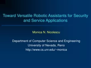
A Versatile Carrier Board and Associated Timer Module Applications Presented byRichard K. Evans R. Evans, A. Grippo, K. Jordan Thomas Jefferson National Accelerator Facility Work supported by, the Joint Technology Office, the Office of Naval Research, the Air Force Research Laboratory, Army Night Vision Laboratory, the Commonwealth of Virginia, U.S. Dept. of Energy under contract DE-AC05-84-ER40150 and the Laser Processing Consortium
Presentation Overview: * Quick look at the FEL User Facility at Jefferson Lab * Short survey of our approach to providing application specific instrumentation and controls * Description of the 6U Versatile Carrier Board Design * Module foot-print and basic function add-on modules * The 4 Channel Programmable Timer Board * Applications of the Timer Boards in FEL Systems * Future of these modular designs * Acknowledgements and Thanks
FEL User Facility First Floor Layout showing 7+ User Labs The Free Electron Laser (FEL) User Facility At Jefferson Lab CEBAF at Jefferson Lab in Newport News, Va. USA
Our Approach To Providing The FEL Control Systems * Copy as many CEBAF system designs as possible. (i.e. LINAC, RF, LLRF, BPMs, Magnet Power Supplies, Vacuum, etc...) * “New system designs” reserved for systems which are: a) unique to the FEL (i.e. LPSS, OTS, Multipass BPMs, DLPC) b) where previous solutions are obsolete (BLMs, Viewer Ctrl) c) where significant advantages are gained by using a new approach. (i.e. MPS, BPMs, ) * “As-Needed” Solutions to System Integration and Evolving System Requirements driven by the experiences gained by operating the FEL.(Timing System (OBPMs), User Support, ... “Application Specific” I&C) And we all know... “The Devil is in the details”
Results of a self-survey of various in-house solutions * Custom Chassis and Box Designs are not efficient.(AC/DC power issues, bulky, not very space efficient, cooling issues) * Most VME crates have at least 1 “one-of-a-kind”widget • Many of the VME cards built do not need to ‘talk’ to the VME Bus • The convenience of the crate Power Supply allows for simple solutions • The 6U form factor provided adequate space for every widget function • Simple Digital I/O • S&H, ADC and DAC • Timing/Delay Generators • Simple PLD logic • 50/75 ohm Signal Distribution • Logic Conversion (24V, TTL, etc...) • Relay Interlocks and Digital Isolation • Fiber Optic Interfaces (Heartbeat to Logic) * Still designing VME but... “the writing is on the wall” • Embedded IOCs are will be commonplace in the very near future • CAN bus I/O is an under-utilized technology (by us) So..., Lets standardize the widget cards into a family ofGENERAL PURPOSE MODULES which can be used on a generic (versatile) 6U form factor carrier card.
* * Board space is divided into 4 equal sections * * P1 * - A P3 connector allows front to back throughput * - Each Side has a 16 pin Local-Bus (A & B busses) P3 P2 - Bus “A”(*) has a set of 16 lines shared I/O and 8 distributed pins for various power * * - Bus “B” (*) has a set of 16 lines shared I/O and 8 distributed pins for serial communications * * Carrier Board Design * 6U Form Factor - Standard VME P1 & P2 - P2 has 64 user def. pins - Each Module gets 16 I/O from P2 onto a 40 pin Conn. - Module A/Slot A is “Special” because it has access to a VME Interface connector (*)
Module foot-print ... and ... some basic function add-on modules • Simple Digital I/O • ADCs and DACs • Timing/Delay Generators • Simple PLD logic • 50/75 ohm Signal Distribution • Logic Conversion (24V, TTL, etc...) • Relay Interlocks and Digital Isolation • Fiber Optics Interfaces (Heartbeat to Logic)
Module foot-print ... and ... some basic function add-on modules
6U - 12 Channel BLM Card with the ‘Modular’ VME Interface I/O
Applications of the Timer Boards in FEL Systems • Drive Laser Pulse Controller (DLPC)Providing Highly Configurable Digital Timing Control of the Drive Laser’s Electro-Optical Cells allows us to: • Macropulse Pulse Repetition Rate • Macropulse Duty Factor (Pulse Width) • A/C Line Lock (60Hz, 30Hz, 20Hz, ..., 0.5 Hz, etc...) • Synchronize with the M.O. (at 37.425 MHz) • Auto Phase Rotate (Line Phase, i.e. 60Hz) • Asynchronous Repetition Rates (f < 10MHz) • Pre-trigger Delay (Mechanical Shutter, Happek, M55, ...) • Beam Sync locked to M.O. • External Trigger for Beam Pulse • N-Pulse mode from EPICS
Applications of the Timer Boards in FEL Systems (cont...) • Multipass BPM timing at 1.169 MHz (M.O.=1497 MHz) / (40) / (25) = (M.O. / 1280) Path Length = 129.87 m ~433ns multipass delay
Applications of the Timer Boards in FEL Systems (cont...) • Multipass BPM timing at 1.169 MHz (M.O.=1497 MHz) / (40) / (25) = (M.O. / 1280)
Applications of the Timer Boards in FEL Systems (cont...) • Multipass BPM timing at 1.169 MHz (M.O.=1497 MHz) / (40) / (25) = (M.O. / 1280)
The Future of these modular designs... • This versatile system of boards has been designed with two primary purposes in mind:- 1) To address aspects of system integration that has “slipped between the cracks” and has no formal solution and to standardize these components. - 2) To minimize the overhead in testing out new ideas and providing solutions which can be provided early while the formal systems are designed. • They are much better than the one-of-a-kind PCBs that we have had in the past (and still do in some places ___shhhh.). • In certain applications like the DLPC, they are now a permanent part of the FEL control system.
Acknowledgments and Thanks ... • I would like to thank and acknowledge the following people and organizations for their specific contributions to this work: • Al Grippo – for his part in developing the EPICS applications • Kevin Jordan – for his approval and guidance • My partners in the FEL I&C group and the entire FEL Team • DOE, ONR, JTO & the AFRL for their continuing investment in the Free Electron Laser Project at Jefferson Lab • and ‘you’ who have provided me this opportunity to present this work at the 10th ICALEPCS 2005. - thank you