Download
1 / 103
1.04k likes | 1.08k Views
Explore the innovative features and advanced technology of our air-cooled inverter chillers. Discover detailed components, schematic diagrams, inverter technology, control algorithms, and self-diagnosis capabilities for efficient troubleshooting. Our product lineup includes models with true dual circuits and inverter compressors for higher performance and energy efficiency. Installation is modular, allowing for easy network setup and operation control through a microprocessor controller. Safety protections and quality components ensure reliable operation. Learn about the benefits of inverter technology and how it enhances system reliability and efficiency. Control algorithms help optimize compressor performance and cooling modes for superior functionality.

E N D
Content • Product Lineup & Features • Components • Schematic diagram • Inverter technology • Control Algorithm • Chiller Panel Controller • Self diagnosis & Troubleshooting • Installation
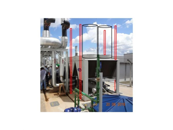
Product Lineup 5ACV100/135/210 CR 5ACV55/75 CR 5ACV30 CR
Features New Technology BPHE- True Dual Circuits Conventional Back to Back Circuits BPHE Secondary Circuit Primary Circuit 1 Primary Circuit 2 5ACV True Dual Circuits BPHE Primary Circuit 1 Primary Circuit 2
Features Inverter Compressor Conventional System Inverter System
Features Higher Seasonal EER Inverter is based on ESEER due to part loading (25%-50%-75%-100%).
Features Elimination of Water Tank Inverter system provide constant Water Temperature band, or much lesser water temperature fluctuation. With this, water tank of mini chiller system can be eliminated Modular Installation A network up to 50 chillers in a system is possible. Control on the operation of chillers will be done through the microprocessor controller. The external water piping connection can be made either from the left or right side of the unit. Safety Protection • High & Low Pressure Switches • Anti Freeze Protection Sensor • Discharge Temperature Sensor • Over Pressure Relief Valve • Water Pressure Differential Switch • Anti Freeze Heater on BPHE • Compressor, Water Pump Overload Protector
Fan guards Coil guards Variable speed fan motors (100%, 70% & 50%) Heat exchangers with gold fin as standard True dual circuits BPHE (Brazed plate heat exchanger) Water pump Expansion tank ( 8L) Control box assembly Components
High pressure switch (NC) 600 psi – open, 480psi – close. EXV (Electronics expansion valve Low pressure switch (NC) 18 psi – open, 28 psi – close. Chiller panel controller Differential pressure switch 4 Way valve Over pressure relief valve Fixed speed scroll compressor (R410A) Anti freeze heater on BPHE Pump OLP (overload protector) Variable speed scroll compressor (R410A) Compressor OLP (overload protector) Variable drive system compartment Fixed drive system compartment Components
3 phase rectifier bridge diode Uni-directional bridge diode PTC starter (Positive temperature coefficient) Fan capacitors IPM board (Intelligent power module) Power board Capacitor board Main board EMI filter Magnetic contactors PFC capacitor (Power factor correction) Components Control box assembly
Schematic diagram Inverter chiller schematic diagram
Inverter technology What Inverter can do for us ? Conventional System Inverter System • Less Start & Stop • Fast Cooling/ Heating • Smart Loading/ Unloading • Better Compressor Reliability
Inverter technology Brief Introduction on Inverter Technology Inverter basic structure Inverter control technology convert AC supply to DC and convert it back to AC. The frequency & voltage of each phase can be controlled and applied on asynchronous motor for variable load control.
Inverter technology Rectification circuit • To minimize emission effect (EMC) and raise immunity level (EMS), a LC filter is used. • PTC resistor acts to cushion start up current to capacitor. • Diode bridge inverts AC to DC.
Inverter technology DC stage • PTC capacitor acts to restraint PF losses caused by fluctuation of DC voltage.
Inverter technology Inversion circuit • Inversion circuits consists of 6 IGBT. (Insulated Gate Bipolar Transistor) • By controlling the linkages, different frequency and 3 phase AC voltage can be generated. • IPM (Intelligent Power Module) encased the inversion circuitry, error detection & protection features.
Inverter technology SPWM ( Sine pulse width modulation ) By computing the on-off frequency and timing of IGBT, a series of output voltage pulse widths can be integrated to form a sine wave for application on VVVF. (Variable Voltage Variable Frequency)
Inverter technology VVVF (Variable voltage variable frequency) • Every inverter chiller has its typical characteristic and VVVF (variable voltage variable frequency) curve. • To control Asynchronous motor, it is desirable to maintain magnetic flux for torque requirement. • Excessive of magnetic flux will cause excitation and diminish the flux. • To maintain optimum flux, the voltage varies with frequency.
Control Algorithm Variable Drive Compressor Control Cooling mode Start up condition : • Pump runs normally for 2 minutes * For example : Return water temp.= 14 to 16 °C Set temp = 12°C D T = 2 to 4°C • 2°C £ T water return – T set£ 4°C • No irreversible errors in variable drive and the systems • Satisfy a delay of 3 minutes before restart # Note : If fixed drive system starts first, the variable drive system should trail after 30 sec. * Depends on Parameter P2 (flow switch alarm delay at pump start. Min 0s, max 199s, default 120s ) # Depends on Parameter C2 (compressor min stop time. Min 0s, max 1990s, default 180s)
Control Algorithm Increase to rated frequency with the rate of 1Hz/s Rated Freq. 55Hz Inverter compressor will start from 5Hz to 55Hz and maintain this frequency for 1 min. 5Hz t 3 min 5 sec 1 min Variable drive comp ON OFF ON OFF Outdoor fan Outdoor fan will start 5 sec before compressor start Cooling mode Cooling mode selected water pump starts Outdoor fan starts variable drive compressor starts 5ACV100CR=75Hz 5ACV135CR=95Hz
Control Algorithm Cooling mode Shut down condition : • Cooling mode terminates, OR • Variable drive system error occurs, OR • T water return – T set£ -2°C For example : Return water temp.= 10°C Set temp = 12°C D T = -2°C
Control Algorithm Heating mode Start up condition : • Pump runs normally for 2 minutes * For example : Set temp = 40°C Return water temp.= 36 to 38 °C D T = 2 to 4°C • 2°C £ T set - T water return£ 4°C • No irreversible errors in variable drive and the systems • Satisfy a delay of 3 minutes before restart # Note : If fixed drive system starts first, the variable drive system should trail after 30 sec. * Depends on Parameter P2 (flow switch alarm delay at pump start. Min 0s, max 199s, default 120s ) # Depends on Parameter C2 (compressor min stop time. Min 0s, max 1990s, default 180s)
Control Algorithm Increase to rated frequency with the rate of 1Hz/s Rated Freq. Inverter compressor will start from 5Hz to 45Hz and maintain this frequency for 1 min. 45Hz 5Hz t 3 min 10 sec 1 min Variable drive comp ON OFF ON OFF Variable 4WV ON OFF Outdoor fan 5 sec Outdoor fan will start 5 sec before compressor start Variable drive 4WV start 10 sec before compressor start Heating mode Heating mode selected water pump starts Variable drive 4WV engages Outdoor fan starts compressor starts 5ACV100CR=65Hz 5ACV135CR=90Hz
Control Algorithm Heating mode Shut down condition : • Heating mode terminates, OR • Variable drive system error occurs, OR • T set - T water return£ -2°C For example : Set temp = 40°C Water return temp = 42°C DT = -2°C
Control Algorithm Fixed Drive Compressor Control Cooling mode Start up condition : • Pump runs normally for 2 minutes * For example : Water return temp = 16°C Set temp = 12°C DT = 4°C • T water return – T set > 4°C Fixed drive starts first followed by variable drive • No irreversible errors in fixed drive and the systems • Satisfy a delay of 3 minutes before restart # Note : If variable drive system starts first, the fixed drive system will only start after the frequency of variable drive drops to 50Hz. * Depends on Parameter P2 (flow switch alarm delay at pump start. Min 0s, max 199s, default 120s ) # Depends on Parameter C2 (compressor min stop time. Min 0s, max 1990s, default 180s)
Control Algorithm Fixed drive compressor starts ON Fixed drive comp OFF 3 min 5 sec 1 min ON Outdoor fan OFF Outdoor fan will start 5 sec before compressor start Outdoor fan will stop after compressor has stopped for 1 min Cooling mode Cooling mode selected water pump starts Outdoor fan starts compressor starts
Control Algorithm Cooling mode Shut down condition : • Cooling mode terminates, OR • Fixed drive system error occurs, OR • T set-T water return > 2°C and variable frequency drops pass 20Hz For example : Set temp = 12°C Water return temp = 10°C DT = 2°C
Control Algorithm Heating mode Start up condition : • Pump runs normally for 2 minutes * For example : Set temp = 40°C Water return temp = 36°C DT = 4°C • T set - T water return > 4°C • No irreversible errors in fixed drive and the systems • Satisfy a delay of 3 minutes before restart # Note : If variable drive system starts first, the fixed drive system will start after the variable drive frequency drops to 50Hz. * Depends on Parameter P2 (flow switch alarm delay at pump start. Min 0s, max 199s, default 120s ) # Depends on Parameter C2 (compressor min stop time. Min 0s, max 1990s, default 180s)
Control Algorithm Fixed drive compressor starts ON Fixed drive comp OFF 1 min 10 sec 3 min ON 5 sec Variable 4WV OFF ON Outdoor fan OFF Outdoor fan and 4WV will stop after compressor has stopped for 1 min Fixed drive 4WV start 10 sec before compressor start Outdoor fan will start 5 sec before compressor start Heating mode Heating mode selected water pump starts Fixed drive 4WV engages Outdoor fan starts compressor starts
Control Algorithm Heating mode Shut down condition : • Heating mode terminates, OR • Fixed drive system error occurs, OR • T water return - T set > 2°C For example : Water return temp = 42°C Set temp = 40°C DT = 2°C
Control Algorithm Pump Control Pump start up When starting the system, pump will run for 2 minutes * before proceeding to next step. * Depends on Parameter P2 (flow switch alarm delay at pump start. Min = 0s, Max = 199s, default = 120s) Pump shut down After both compressors shut down for 1 minute, pump shuts down.
Control Algorithm Pump Control System error When errors occur in the system and require system to shut down, the pump will shut down 1 minute after the system shuts down. If compressor is not running, the pump shuts down immediately. Note : When changing operating mode or when temperature reaches setting, pump continues to run.
Control Algorithm Heating No error Running 1 hour DT>5°C Switch off conditions • System terminates heating mode OR • Wired handset withdraws auxiliary heating command, OR • System errors trigger alarm and require shut down, OR • When T set – T water return < 2°C X Heating Error DT< 2°C Auxiliary heater control (Info only) Start up conditions • System in heating mode AND • System no error alarm AND • After heating starts for 1 hour and T set – T water return > 5°C The second time start up is not time –dependent. For example: Set temp = 40°C Water return temp = 34°C D T = 6°C
Control Algorithm EXV control (Electronic expansion valve) • When system operates for the first time, EXV will operate to preset openings. • After system operates for 10 minutes, the EXV will preset to superheat regulation for variable drive system.
Control Algorithm Select heating mode 4 WV engage 5 sec Heating starts Stop heating mode compressor stops 4 WV disengage 60 sec Compressor crankcase heater control • Fixed drive compressor crankcase heater is driven by the fixed drive contactor (NC). • Variable drive compressor crankcase heater is driven by main board relay. • Crankcase heater will be ON whenever compressors are not in operation. 4 way reversible valve control • When selecting heating mode, 4 way valve will engage 5 seconds before heating start up. • When heating stops, 4 way valve will disengage 60 seconds after compressor stops.
Control Algorithm Outdoor fan control Control basic • Fixed drive and variable drive outdoor fan are independently controlled. • During start up, fan operates at fixed speed. During operation, fans operate at variable speed. • There are 3 fan speeds in High, Medium and Low fan speed. • The High fan speed is 680 RPM and 3800CFM for each fan motor. • The ratio of fan speed is 100%, 70% and 50% respectively.
Control Algorithm Outdoor fan control Fan control for Cooling • Within 20 minutes of normal operation, when Te (Outdoor ambient temp.) ³ 28°C, fan operates at highest speed. • Within 20 minutes of normal operation, when Te (Outdoor ambient temp.) <28°C, fan operates at medium fan. • After normal operation for 20 minutes, when 40°C < (Ta3, Tb2) < 48°C, the fan operates to variable speed (PI regulation). The lower the temperature the lower the speed. Ta3, Tb2 Ta3 = condenser outlet temp. (Variable drive system) Tb2 = condenser outlet temp. (Fixed drive system) PI = program intelligent High fan zone 48°C Constant fan speed control zone PI control zone 40°C Te ³28°C (High fan) Te < 28°C (Med fan) Low fan zone 20 min
Control Algorithm Te Low fan PI control 12°C Constant fan speed control zone (medium fan) 10°C Constant fan speed control zone (high fan) High fan High fan t Outdoor fan control Fan control for Heating • When Te (Outdoor ambient temp.) < 10°C, fan operates at highest speed. • When 10°C £ Te (Outdoor ambient temp.) £12°C, fan operates at medium fan. • When Te (Outdoor ambient temp.) > 12°C, fan operates at variable speed to PI regulation. The higher the temperature the lower the speed. PI=program intelligent
Control Algorithm Defrost start Defrost end 70 Hz Variable drive comp 30 Hz 30 Hz Resume heating mode Variable 4WV Outdoor fan Outdoor fan control Fan operation during defrosting Fan stops 1 minute after the compressor stops.
Control Algorithm Run 5 min/hr ON Water pump Antifreeze heater ON °C System enters heating mode 2 5 6 30 Water return temperature/Outdoor ambient temperature Anti freeze heater control Anti freeze on/off control during system standby • Runs when system in standby mode • If Te (outdoor ambient temperature)£ 5°C and T water return£ 5°C, water pump runs 5 minutes every hour and antifreeze heater will run on and off together with the water pump. • If T water return > 6°C water pump and antifreeze heater will stop. • If Te £ 2°C and T water return£ 2°C, system enters heating mode and returns to standby when T water return > 30°C
Control Algorithm Factory setting for antifreeze heater = 5°C alarm set point = 3°C Antifreeze heater ON °C 3 5 7 Water leaving temperature Alarm on Alarm off Anti freeze heater control Anti freeze during cooling • When T water leaving£ 5°C, antifreeze heater will operate until T water leaving > 7°C. • When T water leaving£ 3°C, alarm will set off until T water leaving > 5°C.
Control Algorithm Manual defrosting Manual defrosting can be carried out when Ta3 or Tb2 < 7°C Defrosting control Automatic defrosting Shall satisfying the below automatic defrosting condition for 3 minutes : • Compressor operates continuously for at least the duration of the defrosting interval. • When Ta3 or Tb2£ 0°C * OR • When T water return > 18°C * Depends on Parameter D1 (Start defrost temperature. Min -20°C, max 14°C, default 0°C ) Ta3 = condenser outlet temp. (Variable drive system) Tb2 = condenser outlet temp. (Fixed drive system) Note : Factory defrost interval depends on Parameter D4 (Defrost interval time). Intelligent defrost interval varies. Under Parameter defrost mode, Intelligent defrost is set as default under DISABLE mode. Factory standard defrost will be activated when the parameter is set to ENABLE.
Control Algorithm Defrost start Defrost end 90 Hz Variable drive comp Resume heating mode 30 Hz 30 Hz Variable 4WV ON OFF Outdoor fan ON OFF Defrosting control Defrosting process Variable drive defrosting process • When defrosting conditions are met for variable drive, variable drive compressor stops outdoor fan stops 4WV disengages variable drive starts defrost at 90Hz. • When variable drive defrosting terminates, variable drive compressor stops 4WV engages outdoor fan starts variable drive compressor starts Resume heating operation.
Control Algorithm Defrost start Defrost end Resume heating mode Fixed drive comp ON OFF 15 sec 10 sec 10 sec ON OFF Outdoor fan 2 sec ON OFF 4WV 2 sec 2 sec Defrosting control Defrosting process Fixed drive defrosting process • When defrosting conditions are met for fixed drive, fixed drive compressor stops (15 sec) outdoor fan stops (2 sec) 4WV disengages (10 sec) fixed drive compressor starts defrost • When fixed drive defrosting terminates, fixed drive compressor stops outdoor fan starts at high speed for 30 sec 4 WV engages Fixed drive compressor starts Resume heating operation.