Download
1 / 17
170 likes | 244 Views
Design and Tests of a New Rest Gas Ionization Profile Monitor Installed in the SPS as a Prototype for the LHC BIW 04 May 3-6, 2004 –Knoxville, Tennessee C. Fischer, J. Koopman, D. Kramer, R. Perret, M. Sillanoli CERN – Geneva - Switzerland. Acknowledgements. AT/VAC/SL: monitor conditionings

E N D
Design and Tests of a New Rest Gas Ionization Profile Monitor Installed in the SPS as a Prototype for the LHCBIW04May 3-6, 2004 –Knoxville, TennesseeC. Fischer, J. Koopman, D. Kramer, R. Perret, M. SillanoliCERN – Geneva - Switzerland C. Fischer-BIW04-May 3-6, 2004-Knoxville, Tennessee
Acknowledgements • AT/VAC/SL:monitor conditionings • ES/MME & PH/TA1:coatings • D. Cornuet and Co.:magnet measurements • G. Arduini:monitor insertion in SPS • A. Beuret:magnet power supplies • A. Guerrero:software requests • B. Dehning, F. Roncarolo: wire scanner data • and all others…. C. Fischer-BIW04-May 3-6, 2004-Knoxville, Tennessee
Outline • The New Monitor magnet central detector tank and assembly • Commissioning in 2002 • The year 2003 problems & cures results • Preparation & Perspectives for 2004 C. Fischer-BIW04-May 3-6, 2004-Knoxville, Tennessee
New Rest Gas Monitor • Encouraging results were got since the installation in 1999 of a prototype provided by DESY and modified to use signal from electrons. • It has been decided to equip the LHC with 4 gas monitors (one H, one V, in each ring). • Continuous profile measurements also needed in the SPS for the LHC era. • Prototype design compatible with LHC requirements: transversespace contingencies→compactness impedance budget→ no big discontinuities in the tank smooth transitions, • e- signal → B field required • Conventional magnet found with 200 mm gap, fulfilling space requirements new gas monitor designed accordingly, manufactured in 2001 and installed in the SPS for the 2002 run C. Fischer-BIW04-May 3-6, 2004-Knoxville, Tennessee
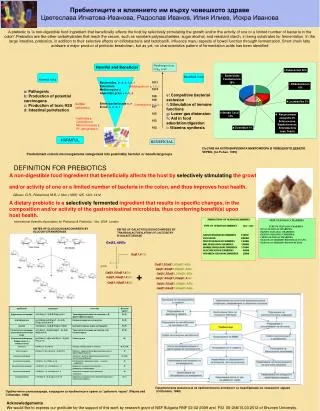
New Rest Gas Monitor: the magnet (1) • magnet recuperated from LEP with following characteristics: Imax = 55 A B max= 0.25 T Strength = 0.14 Tm Gap width : 200 x 200 mm2 Overall length 680 mm section: 681 x 646 mm2 • hole drilled through the yoke for the light signal extraction 3D view 200 mm top view C. Fischer-BIW04-May 3-6, 2004-Knoxville, Tennessee
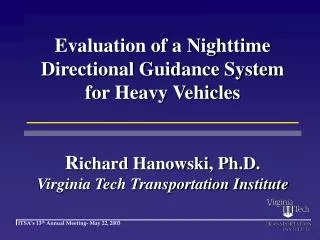
New Rest Gas Monitor: the magnet B linearity B (mT) I (A) Relative B variation along z with x=o at different y Relative B variation along z with y=o at different x % % C. Fischer-BIW04-May 3-6, 2004-Knoxville, Tennessee
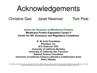
New Rest Gas Monitor: mechanical designThe central detector top view light light e- prism 84 mm MCP cross section view 166 mm 3D view C. Fischer-BIW04-May 3-6, 2004-Knoxville, Tennessee
New Rest Gas Monitor: mechanical designThe tank within its magnet Light signal side view e-signal Light signal F=84 mm 200 mm 3-D view cross section view 680 mm C. Fischer-BIW04-May 3-6, 2004-Knoxville, Tennessee
New Rest Gas Monitor e_ Electric field map As installed in the SPS with 2 corrector magnets used at - B/2 (3 magnet bump) Picture of the assembled central detector C. Fischer-BIW04-May 3-6, 2004-Knoxville, Tennessee
Results from commissioning in 2002 encountered problems:high noise level • electron cloudeffect with LHC type beam evidence : signal increase after injection of 3rd batch effect :electrode DC voltage fluctuations →signal fluctuations • high frequency modes generated by the LHC beam structure inside the detector and in cables effect :HV instabilities, signal loss remedies during 2003 stop • NEG application (TiZrV)on HV electrodes to lower SEY • RF absorbers (filters) close to HV supplies • series resistorsclose to detector feed-throughs • view port conducting cover plateinstalled for better image current conduction C. Fischer-BIW04-May 3-6, 2004-Knoxville, Tennessee
The 2003 campaign (1) encountered problems and cures: • bad electrical contactson phosphor screen after bake-out at 200 C (needed for NEG activation) insertion of thin CuBe frame with flexible contacts • aging of MCP central regiondue to high output signal (test of a fast but less sensitive phosphor) MCP gain decreased and image intensifier added, bump applied to the beam orbit to avoid bad area • limited resolution camera lens diaphragm opening reduced by 50% • lightening on phosphor screen with shortest bunch length series resistors removed • image tilt due to stray B field (through the magnet hole ) on the image intensifier intensifier wrapped with m metal sheets magnet used at 50% of B max C. Fischer-BIW04-May 3-6, 2004-Knoxville, Tennessee
Results from 2003 (1) LHC type beams from pilot to nominal investigated; dynamic in current 104 Pilot: 5.109 p Nominal: 3.5.1013p • = 0.88 mm 450 GeV • = 0.83 mm E= 450 GeV en=3.5 10-6 m C. Fischer-BIW04-May 3-6, 2004-Knoxville, Tennessee
Results from 2003: analysis (3) limitations: electron cloud effect still there (from 3rd batch) → signal increase saturation of MCP at 450 GeV Profile Norm evolution along the cycle C. Fischer-BIW04-May 3-6, 2004-Knoxville, Tennessee
Results from 2003: analysis (4) 75 ns LHC beam: en= 1.4 10-6 m pilot bunch: en= 0.65 10-6 m Limitations, ct’n limited resolution, show-up at 450 GeV for low beam dimensions (s ≤ 0.7 mm) 450 GeV - sthIPM= 0.36 mm smeasIPM = 0.57 mm 26 GeV – sIPM= 1.5 mm Error contribution: 0.35 mm Sources:intensifier residual tilt tails optics: 247 mm /pixel 450 GeV - sthIPM= 0.53 mm smeasIPM = 0.64 mm 26 GeV – sIPM= 2.2 mm C. Fischer-BIW04-May 3-6, 2004-Knoxville, Tennessee
Cures implemented during the 2004 stop (1) • Electron cloud: MCP input face NEG coated • MCP aging and saturation: MCP replaced by a new one, will be operated at lower gain coupled with Low Light Level camera → lower MCP output current suppression of 2 stage amplification → better S/N ratioand resolution more sensitive phosphor layer on new prism: → lower MCP output current CdS:In →Y3Al5O12:Ce (P46) variable gain to be applied during acceleration cycle → to avoid saturation • Resolution limitation: general cleaning of different detector parts replacement of external RF absorbers close to power supplies number of wires on cathode grid decreased by factor 3 →contribution to tails non reflective treatment of support surfaces →to suppress parasitic reflections new optics in front of the camera→ improved opening C. Fischer-BIW04-May 3-6, 2004-Knoxville, Tennessee
Cures implemented during the 2004 stop (3) new optical bench PM tube LLL camera C. Fischer-BIW04-May 3-6, 2004-Knoxville, Tennessee
Perspectives for 2004 With these improvements and a few other upgrades of the control software, all efforts will made during the year 2004 to bring the monitor to an operational stage for the LHC era. A second monitor working in the H plane is approved and is expected for the 2006 SPS start-up. Thank you for your attention C. Fischer-BIW04-May 3-6, 2004-Knoxville, Tennessee