NSTX
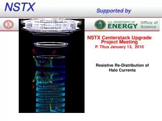
NSTX. Supported by. NSTX Centerstack Upgrade Project Meeting P. Titus/EA Branch Nove3mber 10, 2010. P1 P2 DLF Aluminum Block Bolting Stress Bellows Calc Interfaces. .08e9. P1-P2 Slow. .2e9. P1-P3 Slow. .2e9. .4e9. P1-P4 Slow. P1-P5 Slow. P1-P2 Slow. Dynamic. Static.

NSTX
E N D
Presentation Transcript
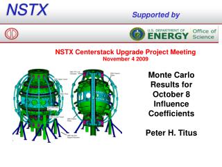
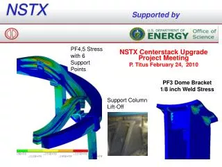
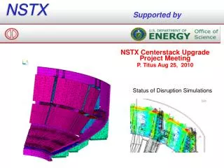
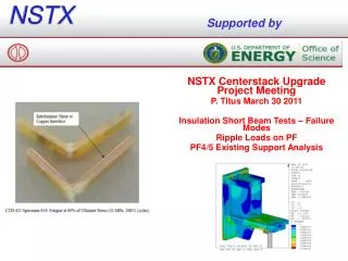
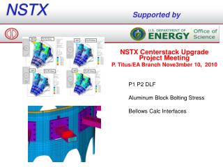
NSTX Supported by NSTX Centerstack Upgrade Project Meeting P. Titus/EA Branch Nove3mber 10, 2010 P1 P2 DLF Aluminum Block Bolting Stress Bellows Calc Interfaces
.08e9 P1-P2 Slow .2e9 P1-P3 Slow .2e9 .4e9 P1-P4 Slow P1-P5 Slow
P1-P2 Slow Dynamic Static Disaplacement DLF = -5.6e-4/(-1e-3) = .56
Better GradeCorner Bolts would be OK – Because of the “Wing” on the back side? HHCS = Hex Head Cap Screw
Pete Rogoff’s Bellows Calculation • Purpose • This calculation is intended to recommend convolution geometry and a thickness of the bellows as an initial sizing exercise, and then provide a performance specification for the purchase of the bellows. Ultimately the bellows manufacturer shall provide the qualification of the bellows, but to ensure an adequate initial design this calculation shall qualify the stress state and performance for the following loading and requirements: • Halo Current Loads (upper bellows only). Reference calculation #NSTX CALC 133-04-00 • The upper bellows must allow thermal motions expected during bake-out, and normal operation in which heat from the plasma is transferred to the centerstack casing through the tiles. Reference Calculation # NSTX CALC-11-01-00 • The bellows must be stiff enough to ensure adequate magnetic stability of the PF1a/OH system (see end of this calc - will be split off in a different calc) • The upper bellows must support the seismic inertia loads Reference Calculation # NSTX CALC 10-01-02 • The upper and lower bellows must transmit some portion of the torsional moment from the outer vessel structure to the centerstack casing. In the centerstack, the casing is a redundant load path for the torsional moment, most of which is transferred through the umbrella structure to inner TF collar. The torsional Shear stresses will be quantified in the global analysis calculation # NSTX CALC 10-01-02. • There may be local moments, or displacements from the vessel or centerstack casing that need to be considered in addition to those predicted by the global model. • Additionally, this calculation will consider and qualify the stresses in the ceramic break and Viton seal. The ceramic break and Viton seal are considered in the global analysis calculation # NSTX CALC 10-01-02, and the inner PF coil calculations #NSTX CALC 133-01-00. Local and detailed stresses in the ceramic break and viton seal will be quantified in this calculation