Download

1 / 15
150 likes | 175 Views
Investigating turbulent flame velocity's role in unconfined explosion consequences, experimental device presentation, mixture preparation, and turbulence characterization. Analysis involves pressure gauges, simulation, and comparison between quiescent and turbulent mixtures. Gülder correlation validates flame turbulent velocity estimation method.

E N D
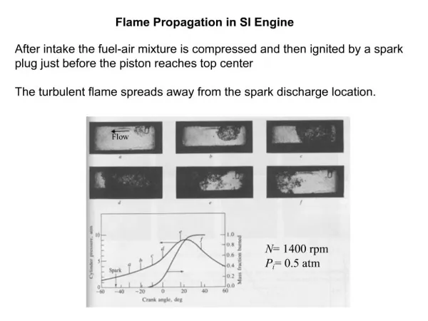
Turbulent flame propagation in large unconfined H2/O2/N2 clouds Jérôme Daubecha, Christophe Prousta,b, Guillaume Lecocqa E-mail: jerome.daubech@ineris.fr a INERIS, Verneuil en Halatte, France b UTC, Compiègne, France
Context • BARPPRO french R&D project – Protection of industrial facilities against explosion blast wave • Turbulent flame velocity – Key aspect to evaluate unconfined explosion consequences • The intensity of flow velocity fluctuations u’ • The characteristic length of vortices Lt • The laminar burning velocity Slad • Link between flame and turbulence Turbulent flow field Laminar flame
Context • Purposes of this presentation : • Presentation of the experimental device • Presentation of the overpressurse and the flame velocities for quiescent and turbulent mixtures • Discussion about flame behavior
Experimental Conditions Test plateform • Metallic structure in 3.5 cm thich IPN structure coverd with a 5 mm metal plate • 1.5 m hemispheric frame formed with 8 flexible plastic tube • 150 µm plastic sheet covers the dome
Experimental Conditions Mixture preparation • Injection of gas thanks to 4 jetflows (coanda effect) • Placed at 0.9 m from center of the plateform • Homogeneous mixture • Creation of turbulent motion
Experimental conditions Instrumentation • Concentration and homogeneity : • Controlled in 2 points at 0.1 m and 1.4 m from the test plateform • Ignition source : • Pyrotechnical match at the center of the hemisphere on the floor • Two pressure gauges Kistler 0-10 bar • At the center of the hemisphere -> Overpressure in the burnt gases • At 10 m from the center of the hemisphere -> Pressure wave
Simulation of this flow field with PIMPLEFOAM Solver (RANS Solver) • Good agreement with the experimental measures Experimental conditions Characterization of turbulence in the dome • Measurement of turbulence with 3 pitot probes in earlier version of test plateform : • Simulation of this flow fieldwith PIMPLEFOAM Solver • Good agreement witjexperimentalmeasures Turbulent intensity : 5 m/s Turbulence lengthscale : 0.15 m • Simulation of experimental situation • Turbulent intensity : 1.5 m/s • Mean turbulent lengthscale : 0.16 m
Flammable mixtures • Stoichiometric hydrogen/oxygen diluted with nitrogen
Quiescent stoichiometric H2/O2 mixture diluted with N2 Mixture 1 : 40 % H2, 20 % O2, 40 % N2 • Burnt gas overpressure and overpressure at 10 m • Maximum overpressure : 250 mbar at 36 ms Fast camera
Flame trajectory and flame velocity Maximum overpressure : 250 mbar at 36 ms Quiescent stoichiometric H2/O2 mixture diluted with N2 Mixture 1 : 40 % H2, 20 % O2, 40 % N2 Part 1 Flamevelocity ~50 m/s Part 2 Flame velocity Increase by 50 to 115 m/s Flame velocity vs distance, spherical explosion of stoichiometric hydrogen-air mixtures – DRENCKHAHN ET AL, 1985 Fast camera Expansion ratio E : 7.5 Laminarflame speed Slad : 3.5 m/s E.Slad = 26 m/s -> Ratio ~2 betweenmeasured and theoreticalflamevelocity Creation of a turbulent/shear flow between the flame front and the plastic envelope Experimental observation consistent with previous works Hydrodynamic instability = self-acceleration of flame Motion of plastic sheetat 22 ms Two distincts part in flame trajectory
Comparison between quiescent and turbulent mixture Mixture 1 : 40 % H2, 20 % O2, 40 % N2 • Turbulence created during gas injection by the 4 jetflows • Burnt gas overpressures for the quiescent and the turbulent mixtures • Quiescent/Turbulent mixtures : • Two parts in pressure signals • Strong pressure rise up linked to the motion of plastic sheet
Comparison between quiescent and turbulent mixture Mixture 1 : 40 % H2, 20 % O2, 40 % N2 • Quiescent mixture – Average flame velocity = 50 m/s • Turburlent mixture – Average flame velocity = 85 m/s x 1.5 Turbulent flamevelocity = 11 m/s
Comparison between quiescent and turbulent mixture Mixture 1 : 40 % H2, 20 % O2, 40 % N2 • Intercomparison between different correlations : • Bray correlation : • Shy correlation : • Gülder correlation : u’ - turbulent intensity, Lt – turbulent length scale, η – flame thickness, K – Karlovitz number Gülder correlation gives the best result and confirms the past INERIS choice to estimate the flame turbulent velocity