Download
1 / 21
210 likes | 300 Views
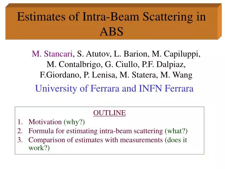
Estimates of Intra-Beam Scattering in ABS. University of Ferrara and INFN Ferrara. M. Stancari , S. Atutov, L. Barion, M. Capiluppi, M. Contalbrigo, G. Ciullo, P.F. Dalpiaz, F.Giordano, P. Lenisa, M. Statera, M. Wang. OUTLINE Motivation (why?)

E N D
Estimates of Intra-Beam Scattering in ABS University of Ferrara and INFN Ferrara M. Stancari, S. Atutov, L. Barion, M. Capiluppi, M. Contalbrigo, G. Ciullo, P.F. Dalpiaz, F.Giordano, P. Lenisa, M. Statera, M. Wang • OUTLINE • Motivation (why?) • Formula for estimating intra-beam scattering (what?) • Comparison of estimates with measurements (does it work?)
ABS Intensity k number of selected states (1 or 2) a dissociation at nozzle exit Qin input flux f fraction of atoms entering the first magnet t magnet transmission, calculated with ray-tracing code A attenuation factor
HYPOTHESIS: the beam density has an upper limit due to intra-beam scattering(IBS) Parallel beam slow fast POSSIBLE WAY TO INCREASE INTENSITY: increase the transverse beam size while keeping the density constant A method for estimating IBS is essential to work near this limit.
Cross Section Definition (for two intersecting beams) dv = Number of collisions in time dt and volume dV n1,n2 = Beam densities Vrel = Relative velocity of the two beams • v1||v2: • General: (Landau and Lifshitz, The Classical Theory of Fields, p. 34, 1975 English edition)
Calculation of IBS losses For scattering within a beam: • Analytical solution, if: • v1 and v2co-linear • constant transverse beam size A Steffens PST97
Simple Example • Remaining flux for r<= 5 mm • Diverging beam from molecular-like starting generator and 2mm nozzle • Dv/v = 0.3 Isotropic direction (random cosq,f) q Random point inside nozzle
Fast Numerical Solution • Begin with a starting generator. • Use tracks to calculate the beam density in the absence of collisions. • Calculate the losses progressively in z. • Approximations: • Uniform transverse beam density • Co-linear velocities • s is temperature (relative-velocity) independent
Calculate n0(z), the nominal beam density without scattering, by counting tracks that remain within the acceptance r<5mm For each piece dzi, reduce the nominal density by the cumulative loss until that point Cumulative loss Calculate the losses within dz, subtract them from ni to get ni` and add them to the cumulative sum Density reduced by scattering
Experimental Tests • Dedicated test bench measurements with molecular beams and no magnets • Compare with HERMES measurement of IBS in the second magnet chamber • Calculate HERMES ABS intensity including the attenuation and compare with measurement
Velocity Distribution Measurement TIME OF FLIGHT FITTED PARAMETERS To be improved:Dv and vmean have 10-20% error and one value is used for all fluxes
Attenuation Prediction MEASURED CALCULATED
Application to HERMES Total density Sum over tracks that pass through dr Total number of tracks Envelope density
Weighted average density: Survival Fraction:
Comparison with measurements • Reasonable agreement! • s(H1-H1) » 3x10-14 cm2 PRA 60 2188 (1999) (calculation) Note that IBS measurement is in a region of converging beam, while calculation assumes co-linear velocity vectors.
What could explain the difference? • Formula assumes that vrel=v1-v2, and this neglects the convergent/divergent nature of the beam • Formula assumes that Dv is constant for the entire length of the beam
Conclusions • The parallel beam equation has been freed from the assumption of constant transverse beam size. • The new equation reproduces molecular beam measurements reasonably well. Some more work remains to be done on velocity measurements and RGA corrections. • The large losses from IBS measured by HERMES in the second half of the ABS are incompatible with the overall losses in the system, given the current assumptions. Predictions can be improved by introducing a z dependence into Dv to account for changing velocity distribution and/or convergence angle. • This attenuation calculation can be done in 1-2 minutes after the average density is obtained, and is thus suitable for magnet parameter optimization
Uncertainties • Starting Generator: E2% on loss • Assumed that tracks with cosq>0.1 leave beam instantly (underestimate losses immediately after nozzle) • Velocity Distribution (mol. beams): E15% on cross section • Neglecting RGA ???