Download

1 / 38
380 likes | 412 Views
Workshop overview on field quality steering, testing procedures, and beam dynamic specifications for magnet production and testing processes. Includes detailed insights on cold testing, geometrical errors, magnetization effects, and cable characteristics.

E N D
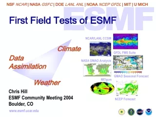
Status of field quality and first trends at 1.9 K L. Bottura and S. Sanfilippo, and the AT-MTM measurement and analysis teams. Workshop on Field Quality Steering of the Dipole Production, 20-21 March 2003.
Overview • General considerations • Field quality at operating conditions. • Main field (field integral,magnetic length, field direction). • Multipoles at injection and collision. • Field component errors. • Geometric errors at 1.9 K and warm/cold correlations. • Effect of the Lorentz force • Iron saturation. • Magnetization effect, cable coupling currents, decay/snap-back. • Conclusions and perspectives.
Scope of the testing at cold.General considerations. • To guarantee that specifications are met. • To complete the production control and late feed-back on parameters that can only be measured cold. • cold geometry (deformations during cool-down and under e.m. loads). • Saturation effect. • SC cable effects • To provide relevant installation data. • quadrupole center, dipole direction • To produce database for LHC magnetic reference(interface to LHC control system). Field errors must be known at operation time to insure that control systems is within its limits.
Beam dynamic specifications.General considerations. • Beam dynamic specifications are given in terms of : • - systematic: average of the averages per arc. • - random : sigma of the multipoles per arc (1/8 of the machine) • - uncertainty : sigma of the average per arc. • (Hard ) specifications at injection and nominal field were defined in the LHC project note 501 (2001) by S.Fartoukh and O.Brüning. • Expected multipoles coming from the different errors sources were presented in a table issue in 1999 by the Field Quality Working Group and updated in August 2001. In this contribution : Integrated (critical) multipoles at injection or collision are compared to lower and upper limits of the systematic (+1 and/or+3 s bounds).
Magnets tested at cold.General considerations. • 24 pre-series cryo-dipoles measured at 1.9 K+1019 under cold test. • - 14 Alstom (100X), 4 Ansaldo (200X), 5 Noell (300X). • - Dipoles 2002 and 3004 : no magnetic measurements. • Striking features of magnet geometry: - 22 magnets with X-section 1 (non corrected for b3 and b5). • - 3 magnets with X-section 2 (1003, 1014,1019). • - 8 magnets with non nominal shims. • - 18 magnets with the 3rd end generation (extra end-spacer with reduced thickness) . • (contribution of S.Russenchuck, M.Modena) • Magnetic measurement at 1.9 K • - without beam screen. • - calculated contribution used : Db3 =-0.424 u, Db5=0.386 u, Db7= -0.244 u) • (simulation by M.Aleksa)
Cables in the magnets.General considerations. • Rutherford cables:multi-strand compacted, keystoned. • - Inner layer : 28 strands ( =1.065 mm, Lp=18 mm), filament 7 mm. • - Outer layer : 36 strands ( =0.825 mm, Lp=15 mm), filament 6 mm. • - Max strand hysteresis spec: 30 mT (inner layer), 26 mT (outer layer) 4.5 %. • - Minimum inter-strand resistance spec: 15 mW. • (contribution of A.Verweij ) • Strand manufacturers (B,C,D,E,G,K) • - 14 magnets with the combinations 01B-02B. • - 2001, 3009 : 2 types of outer layer cables. • (data from the LHC –cable data -base)
Twin coils • 13 segments • 1.25 m module length • 16.25 m total length Stepping motor Twin Rotating Unit Equipment for measurements at cold (1).General considerations. 15-m long twin rotating coils. • Highly efficient through simultaneous measurement of both apertures, full magnet length divided in 12 sectors. • Accuracy: - b1 1 10-4 (1 unit) - harmonics 0.01-0.001 units @ 17 mm. • Field angle: nominal accuracy ±0.2 mrad, however recently large uncertainty ±1 mrad due to mechanical calibration instability
Equipment for measurements at cold (2).General considerations. Single Stretched Wire system. (SSW). • fully automatic system supplied by FERMILAB • 0.1 mm tension-controlled single CuBe stretched-wire • 2 LEICA-referenced precision translation stages • basic working mode used: DC flux sweeping in the vertical and horizontal directions integrated field angle is computed from the ratio (no access to local values) • Measurement precision ±0.2 mrad.
Magnetic measurements in the test flow diagram.General considerations. • Combined with power tests. • Performed after the magnet is trained up to 9 T.
300X dipoles have Bdl above the average. Dipole integrated strength (B1 dl).Field Quality at operating conditions. injection flat-top average (T m) 7.693 119.30 sigma (units) 6.14 5.66 Nom.val. (Tm) 7.655 119.08 Sorting?
Magnetic length. Field Quality at operating conditions. injection flat-top average (m) 14.314 14.315 sigma (mm) 5.7 5.4 Nom.Val (m) 14.300 14.300 different spacers in the magnet ends
Tolerances Dipole field direction.Field Quality at operating conditions. flat-top average (mrad) 0.5 ±1.0 sigma (mrad) 0.8 Tolerances (mrad) ±1 estimate of measurement error with long shaft. Mag_angle:field direction with respect to magnet mid-plane as used for the installation. * * * * * * Measured with SSW Magnets measured with SSW are within the tolerances.
Systematic bounds Syst.+3s bounds Field quality at injection. Magnets with high non-nominal shims. beam frame b5 and b7 out of specs: see geometric errors. b3 random should decrease to about 1.4 units.
Systematic bounds Syst.+3s bounds Field quality at flat-top (7 TeV) Magnets with high non-nominal shims. beam frame • X-section 1 :b3 and b5 out of specs (see geometric errors). • X- section 2 :Gap with specs reduced . b7 is outside the limits.
Study of the field component errors. • cold geometry (deformations during cool-down and under e.m. loads). • Saturation effect at high field. • SC cable effects at injection : • (magnetization, ramp rate induced harmonics, decay/snapback.)
Syst+1s bound Geometric field errors.Field component errors. Magnets with high non-nominal shims. Field frame • X-section 1+high shims: b3, b5 out of specs (by 6 units and 0.5 units). • X-section 2 :Gap with specs reduced . b7 becomes out of the window.
Warm/cold correlations.Field component errors. Courtesy of E.Todesco, V.Remondino.
Warm/cold correlations summary.Field component errors. (wrt ideal corr.line.) (for cold mass) Warm data :Courtesy of E.Todesco, V. Remondino. Good correlation between warm and cold measurements. Discrepancy in b2 (heads) under investigation. Knowledge only through warm measurements may be not enough for operation ? NB :D b3 = 0.4 unit Dx= 20 units, D b5 = 0.2 unit 1 s on D.A.
d = -0.19 • = 0.4 R= 1.57 • d = 3.91 • = 0.48 R=2.15 Warm/cold distribution.Field component errors. Histogram of: D = b3geometric-b3collared-coilD = b3geometric-b3cold-mass The distribution of warm-cold difference is not gaussian . Distribution is not fully stable yet.
3006 3002 ~58 units Saturation summary (1). Integrated transfer function. Model: courtesy M.Aleksa High field behavior of the TF well described by the saturation of the iron.
Systematic Saturation summary (2). Field Component errors. Details Field frame Measurements in accordance with the estimates but Unforeseen saturation effect for b5.
Harmonics at high field Field computation program ROXIE with analytical BEM-FEM coupling methods by S.Russenchuck, M.Aleksa. Very good agreement exp/model for b2 and b4.
Coil movements at high field difference between measured b3 and b5 and multipoles expected at high field variation, averaged over the complete magnet population. Coil movements at high field, initially thought to be negligible, will give a small but visible, systematic effect. Effect to be taken into account in the warm/cold correlation.
Evolution of the geometric multipoles bngeoduring the training of the magnet . (statistic based on 10 magnets) 5-10 % ~20% • b3geo and b5geo vary roughly linearly with IF2 (last current achieved before the Mag.Meas). • The field quality has to measured when the magnet is trained up to 12.85 kA.
Magnetization from iron? Syst+1s bound measured at injection field. Persistent currents. Field Component errors. Beam frame Calculated field errors: R.Wolf et al. LHC Project note 230 (2000). Discrepancy for b1. For the multipoles : Agreement within 10 %. Random match with expectations.
dB/dt eddy current loop cross-over contact Rc Ramp rate induced field errors.Field Component errors. • Heat lossPeddy dB/dt and 1/Rc • Advance in fieldDb1dB/dt and 1/Rc • Allowed and non allowed multipole errorsDbrrn, Darrn. But ifRc too high (>> 100 mW) : Premature quench. R&D to Control Rc : Specified for LHC > 15 mW.
Beam frame expected values at 10 A/s, referred to injection field Syst+1s bound Eddy currents summary.Field Component errors. Calculated field errors based on Rc~15 mW and s~30% for 1/Rc: R.Wolf (2002). Peddy 0.2 W/magnet at 10 A/s Small AC Loss and ramp rate effect on the multipoles. Rc control works (>>30mW) !
Simulated 1800 S 1800 S 760 A 1000 S. QUENCH Decay at injection. Field Component errors. It affects the allowed and non allowed multipoles. Depends on the history of the magnet.
Syst+1s bound Decay at injection. Field Component errors. Short run before injection (30 minutes). Injection plateau of 1000 s. Beam frame Critical for CO distorsions. Max systematic :Db decay max=1/3 Db persistent Multipoles within the expectations. But values increase by 40 % for long run and 10000s injection! Decay of b1 not explained.
Harmonics decay at injection Change of b3 and b5 averaged over the whole magnet length. Short run before injection (30 minutes). Injection plateau of 1000 s. Large spread measured among magnets of the same population. Watch out for changes of local b3 and b5 w/r to average ! NB :D b3 = 0.02 unit Dx= 1 units, D b5 = 0.2 unit 1 s on D.A.
Conclusions (main field). • Standard deviation in the Field Integral at the limit of the specs. Attention is needed to the 300X dipoles! • Field direction : dipoles within the limits at the present state. • High field behavior of transfer function well understood. • Features related to b1 and a1 have to be investigated : • persistent (systematic, spread) • decay
Conclusions (multipoles). • Coil geometry is (at present) the source of largest field errors, (both Systematic and spread). It dominates the F.Q at flat top and injection field. • Improved situation with magnets with nominal shims and X-section 2 but b3, b5 still far from optimal values (by 3.5 and 0.4 units). • Good warm/cold correlation but still early to assess the statistical relevance (distribution?) • Saturation effect: OK But effect of the Lorentz force to be taken into account (geometric, high field behavior for b3 ,b5). • Eddy current errors are well below the allocated budget. • Attention is needed to the other error sources: • persistent (systematic) • decay (spread).
Acknowledgements. - M.Buzio, L. Deniau, V. Granata, R. Mishra, T.Pieloni (AT-MTM) for cold measurement data. -V.Remondino, E. Wildner, E. Todesco (AT-MAS) for warm measurement data. - the AT-MTM measurement team in SM-18.
beam reference y y x x y field reference x x Aperture 1 Aperture 2 Aperture 1 Aperture 2 y Annex 1:Frames
Annex 2: FORMULAS • Transfer function • Field direction
[unit] [unit] Annex 2: FORMULAS Coil 1 Coil 2 Coil 11 Coil 12 12 coils of Li = 1.15 m + 0.11 m of gap B1,i Magnetic field averaged in the coil i B1,12 = B1,1 0.69*B1,6 (from experiment) B=0 Lyre side For each coil (I): i=1,12 : coil ends, the magnetic field in the body is measured by the coils i=2 to i=11 In reality gap correction is applied (invisible to users) See specification in :http://mtauser.home.cern.ch/mtauser/archives/DAP/guides/specsguide
Current cycle or ramp to quench Magnetic measurement bn geometric IF=Imax or IQ 10 A/s 10 A/s (if no quench) 400 A 400 A Annex 3: Training study. Study of bn geometric = f(IF)