Download
1 / 36
360 likes | 390 Views
Explore the latest research on weld solidification behavior, key to understanding properties and performance, enhancing with computational thermodynamics. Learn about solidification modeling applications, thermodynamic fundamentals, and developing interface response functions.

E N D
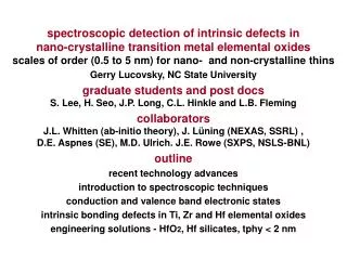
Recent Advances in Modeling of Solidification Behavior J. M. Vitek1, S. S. Babu2 and S. A. David1 1 Oak Ridge National Laboratory 2 formerly ORNL, now at Edison Welding Institute Presented at Trends 2005 Pine Mountain, Georgia May 16 to 20, 2005
Acknowledgements • This research was sponsored by the programs within the U. S. Department of Energy, under contract DE-AC05-00OR22725 with UT-Battelle, LLC: • Division of Materials Sciences and Engineering • Advanced Turbine Systems Program, Office of Fossil Energy • NNSA Initiatives for Proliferation Prevention Program • The authors would also like to thank General Electric Corporation for providing the Rene N5 alloy.
Understanding Weld Solidification is Critical • Solidification behavior determines weldability and solidification structure controls properties and performance • Weld solidification is related to casting but it has many unique features • High growth rates, cooling rates and thermal gradients • Vigorous fluid flow • Epitaxial growth • Conditions that vary with position
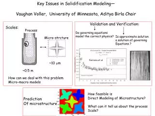
Modeling Provides the Path Toward Understanding Weld Solidification Behavior
Outline • What I will cover: • Thermodynamic, kinetic and phase transformation modeling applied to solidification • Interface response functions • Welded single crystal grain structures • Phase field modeling • What I won’t cover • Heat and fluid flow modeling • Recurring theme: integration of models
I. Computational Thermodynamics: The Backbone of Advanced Models • Need to know the phase diagram (phase stability for multicomponent systems and as a function of temperature) • Need to identify solute redistribution • Computational thermodynamics (CT) addresses all of these
Solidification Involves: • Competition among primary phases • Stabilization of non-equilibrium phases as a result of segregation • Non-equilibrium solidification temperature ranges, often well beyond equilibrium ΔT • Solute redistribution, strongly affected by solidification morphology, and vice versa • Solidification structure and solute distribution that influence solid-state transformations, in-service behavior, stability, etc CT provides the basis for quantifying all of these
CT Has Advanced Significantly in the Last 10 Years • Many more systems are covered, including specialty databases • Thermodynamic databases are more accurate • CT can be used extensively in IRF models, phase field models, etc
Ex 1:Sample Scheil Simulations • For IN718 alloy • To 99% solid • Routines also available for partial inclusion of solid state diffusion
Ex 2: Diffusion Kinetics Models Interface with CT • Include: • Solid state diffusion • Scaling effects • Undercooling • Classic application is to interdendritic segregation
But Diffusion Kinetics Models Can Be Used for Much More • Consider Al-4 wt % Cu system • 10 µm cell size • Consider only primary FCC solidification • Follow profiles versus time L time
Interdendritic Effects Can Be Examined • Standard dendrite theory considers only isolated dendrite • Can model dendrite shape • Between dendrites have undercooling and segregation which may lead to: • New dendrites • New grains • New phases
Dendrite Shape and Interdendritic Undercooling in Al-4Cu liquid solid μm μm Arbitrary thermal gradient (1.3 x 10⁶ K/m) was used and this determines vertical length
Example 3: Kinetics Calculations Explain FN Distribution in Castings • FN distribution in 316SS can’t be explained by: • Solidification mode change • Intuitive solid-state transformation behavior • Combined with thermal profiles, kinetics calculations solve problem High FN Low FN
FN Distribution Is a Combination of Solidification and Solid State Cooling Rates Center Edge
II: Interface Response Functions • IRF calculates growth front undercooling as a function of solidification phase and its morphology • Non-equilibrium effects are taken into account • IRF identifies solidification phase (when competition is possible) and solidification morphology (planar front, dendritic) Based on work of Kurz and co-workers.
Maximum Intensity Cooling arc-off In-Situ Experiments Showed a Solidification Mode Change in Fe-Mn-C-Al to Austenite Solidification at High Solid-Liquid Interface Velocities Background
arc-off Cooling Slope-start TRXRD Measurements Conclusively Confirmed Equilibrium d-Ferrite Solidification Mode at Lower Cooling Rates • This is confirmation that switching occurs as a function of interface velocity.
IRF Calculations for Fe-C-Al-Mn Agree with Experiment Only If Parameters Are Changed • Calculations depend on • kv, Partition coefficient = f{Velocity, Temperature} • mV, Liquidus slope = f{Velocity,Temperature} • R, Dendrite tip radius = f{kv,mv} • Cl*, Interface concentration = f{kv} • Gibbs Thompson coefficient
III: Solidification Grain Structure in Welded Single Crystals • Single crystals represent a technologically important class of materials • Successful welding of single crystals, yielding crack-free single crystal welds, is needed • Modeling of solidification behavior in single crystals is needed to understand and advance this technology • Modeling has identified mechanism of stray grain formation
200µm Avoiding Stray Grains Is the Key to Welding Single Crystals Fe-15Cr-15Ni: perfect, no stray grains Ni superalloy: lots of stray grains and cracks
Proper Evaluation Must Combine Several Sub-Models • Heat and fluid flow to identify weld pool shape and solidification conditions along weld pool (thermal gradient, solidification front velocity) • Geometrical model identifies active base metal dendrite growth direction as a function of solidification front orientation • Nucleation and growth model identifies tendency to form new (stray) grains
Schematic of problem and contribution of each model • Heat and fluid flow model • ID weld pool shape • ID thermal gradients • ID growth velocity as f(weld speed) • Geometric model • Relate dendrite orientation to solidification front • Relate dendrite growth velocity to solidification front velocity • Nucleation and growth model • Relate formation of new grains ahead of SF to undercooling ahead of dendrites
G = thermal gradient V = growth velocity N0 = nucleation rate Φ = stray grain volume fraction a, n = material constants or Φ was calculated over the entire weld pool since V, G vary; it was calculated for many different weld powers, speeds, and crystallographic orientations where Theory for Extent of Constitutional Supercooling Has Been Derived by Gäumann et al
Calculations Predict Stray Grain Formation Tendencies • Find range of probabilities over entire pool • Find effect of weld conditions on tendencies
Tendency to Form Stray Grains as a Function of Location Was Found Symmetric, high speed Symmetric, low speed Asymmetric, low speed Blue = low likelihood of stray grains, Red = high likelihood of stray grains.
The Optimum Weld Processing Conditions Could Be Identified Low power and high speed yield the lowest predicted values of Φ
IV: Phase Field Modeling Offers Many New Possibilities • Phase field modeling is a mathematical formulism that allows for the solution of many difficult but important problems • Phases, compositions, grain orientations are described with diffuse boundaries • Phase transformations, grain growth, recrystallization can all be modeled • Integration with CT provides solid basis for considering multi-component, multi-phase systems
Advantages and Disadvantages of Phase Field Modeling Advantages • Multidimensional • Can handle multi-component systems with slow and fast diffusers • Models spatial distribution Disadvantages • Computationally intensive • Need to identify critical parameters • Anisotropy • Surface energy • Nucleation density, etc
Commercial Software (MICRESS) Is Available and Was Used • Fe- 1 at % C- 1 at % Mn • System parameters • 0.75 x 1.5 mm size • Cooling rate of 10K/s • Thermal gradient of 25 K/mm • Primary BCC (5 grains); nucleation of FCC (15 nuclei) • BCC anisotropic; FCC isotropic
Solidification Movie • Shown: • Development of dendritic structure • DAS spacing • Accommodation of secondary arms • Interdendritic nucleation of secondary FCC • Overtaking of dendrites by secondary (FCC) phase • Could extend to: • Stray grain formation • Growth behavior as function of dendrite orientation • Phase competition
Phase Field Calculations Provide Important Additional Information
Phase Field Fills in the Gaps • Adds dimensionality to kinetics (Dictra is 1D) • Adds multi-phase and directly includes thermodynamics • Describes morphology and distribution, not just amounts of phases (as CT and Dictra) • Could extend to look at stability in service – how non-equilibrium phases and solute segregation will evolve during high T exposure
But Phase Field Has Problems • Parameters may not be known very well • Nucleation rate, nucleation conditions • Anisotropy and orientation dependence of parameters (surface energy, etc) • Computational time • Movie took 60 hours of CPU • But parallel operations are near • Problem will diminish with time
Summary • Key components of quite sophisticated models are available • Integration is the key • See model integration more and more; advances will be in terms of added sophistication of component models • Problem of identifying parameters, their reasonable values, and determining sensitivity to accuracy of parameters