Download
1 / 17
170 likes | 206 Views
Learn about sampling, Fourier transform, spectrum, reconstruction, downsampling, upsampling, filtering, ADC, DAC, and practice examples in signal processing.

E N D
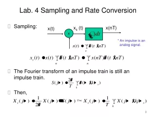
Lab. 4 Sampling and Rate Conversion • Sampling: • The Fourier transform of an impulse train is still an impulse train. • Then, xs (t) x(nT) x(t) x * An impulse is an analog signal.
Spectrum: • Reconstruction: Sampling xs (t) x(nT) x(nT) Ideal LPF x
Practical sampling device (ADC): * FLASH ADC
Successive approximation ADC: * Tree search
Downsampling: • Let m=i+kM and we have Xd(n)= x(Mn) x(n)
Spectrum: • To avoid aliasing, a filter is generally applied before the downsampling operation. • Upsampling: i=1 i=1 i=0 i=0 i=0 Xd(n)= x(Mn) x(n) LPF Cutoff=/M Gain=1 Xu(n)= x(n/L) x(n)
The spectrum: Ideal LPF
The upsampling process is then equivalent to increase the sampling rate by a factor of L. • The filtering operation is also known as interpolation. Gain=L Xu(n) x(n) LPF Cutoff=/L
Practice 1: • Generate a sinusoidal signal, downsample the signal, and observe the its spectrum. • Determine the maximum downsampling rate such that the aliasing will not occur. • Then upsample the downsampled signal, and observe its spectrum.
General filter design: • Pass band • Stop band • Transition band • Passband ripple/stopband ripple A lowpass filter
The analog filter design (IIR): • 1. Butterworth, 2. Chebychev I, 3. Chebychev II, 4. Ellipic
Practice 2: • Generate a sinusoidal signal, downsample the signal (no aliasing), and then upsample the downsampled signal. • Design an FIR LPF and let the upsampled signal pass the filter such that the upsampled signal is similar to the original signal. • Calculate the MSE of these two interpolation schemes.
Practice 3: • Create an random digital signal and upsampled it with a selected factor. • Observe the spectrum of the upsampled signal. • Reading assigment: • Pulse shaping (CS: 4.5) • RC, SRRC
Filter design(FDA tool) • Key “fdatool” in the console of MATLAB • Adjust parameters for your requirement • Press “Filter coefficients” to get filter time-domain response h[n] • Convolve h[n] in your C program to implement lowpass filtering • Plot spectrum in MATLAB • Plot( abs( fft( x ) ) ) • fft(): Fast Fourier Transform, frequency interval is [0 fs] • abs(): get magnitude