APPLIED ELECTRONIC CIRCUIT
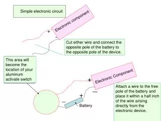
APPLIED ELECTRONIC CIRCUIT. 2012101224 차 온 유. APPLIED ELECTRONIC CIRCUIT. Chapter.3. APPLIED ELECTRONIC CIRCUIT. Passive Filter. 중요한 특징 : 증폭이 없다 . (Op-Amp 를 가지고 있지 않음 ). RC Filter 주로 저역통과 필터로 사용된다 . 저항 R 과 커패시터 C 를 신호원에 직렬로 연결하고 C 의 양단에서 출력을 뽑는 방법으로 사용한다 . .


APPLIED ELECTRONIC CIRCUIT
E N D
Presentation Transcript
APPLIED ELECTRONIC CIRCUIT 2012101224 차 온 유
APPLIED ELECTRONIC CIRCUIT Chapter.3
APPLIED ELECTRONIC CIRCUIT Passive Filter 중요한 특징 : 증폭이 없다. (Op-Amp를 가지고 있지 않음) • RC Filter • 주로 저역통과 필터로 사용된다. 저항 R과 커패시터C를 신호원에 직렬로 연결하고 C의 양단에서 출력을 뽑는 방법으로 사용한다. • LC Filter • 공진하는 필터로 특정 주파수에서 주파수 선택적 특성을 가진다. 정확히 공진하게 되는 주파수는1/d(LC)^(0.5)s Radian으로 나타낸다. • 이것은 특정한 주파수를 통과시키거나 반대로 막을 수 있기 때문에 필터로 사용된다.
APPLIED ELECTRONIC CIRCUIT Active Filter 중요한 특징 : Op-Amp를 사용하고, 이득을 구현할 수 있다. Low-pass Filter High-pass Filter • 연산 증폭기에 대하여 저항(R)은 직렬로, 커패시터(C)는 병렬로 연결하여 구성 • 가장 간단한 형태로 구현되어 모든 필터의 기본형으로 쓰임 • 주어진 차단 주파수보다 낮은 주파수 대역은 통과시키고, 이보다 높은 주파수 대역은 감쇠시킴 • 저역 필터의 저항(R)과 커패시터(C)의 위치를 바꾸어 구성한 회로 • LPF와 정반대라서 자주 쓰일 것 같지만, 실제로는 매우 제한된 용도로 사용됨 • 주어진 차단 주파수보다 높은 주파수 대역은 통과시키고, 이보다 낮은 주파수 대역은 감쇠시킴
APPLIED ELECTRONIC CIRCUIT * Ideal Filter Response Curves * Real Filter Response Curves
APPLIED ELECTRONIC CIRCUIT * Capacitor 필터를 구현하기 위해서 커패시터, 인덕터가 꼭 필요하다!!!!! * Inductor
APPLIED ELECTRONIC CIRCUIT Rational Function Transfer Function Rational Function Pole - Zero diagram Left Half Plane Right Half Plane
APPLIED ELECTRONIC CIRCUIT First Order Active Filter 1. Low-pass Filter Low-freq gain(DC gain)
APPLIED ELECTRONIC CIRCUIT 2. High-pass Filter High-freq gain
APPLIED ELECTRONIC CIRCUIT 3. Band-pass Filter Pass-band gain Low 3dB cutoff freq High 3dB cutoff freq
APPLIED ELECTRONIC CIRCUIT 4. Phase-shifter - 0dB = 이득이 ‘1’(증폭에 감쇄가 없다!) 입력이 출력에 그대로 나온다. - 위상이 주파수에 비례 (Time delay가 주파수 별로 같다!) Phase distortion이 안 일어난다.
APPLIED ELECTRONIC CIRCUIT Second Order Active Filter Undamped: Underdamped : Overdamped: Critically damped :
APPLIED ELECTRONIC CIRCUIT 1. Low-pass Filter • = LPF의 DC gain(상수) 주파수에 따라 변하는 성분
APPLIED ELECTRONIC CIRCUIT 상수가 된다.(DC일 때 일정한 값에서 시작) 10배씩 변할 때마다 40dB씩 줄어든다. 필터로 생각했을 때, 2차 필터가 더 좋다! (특정 주파수 이상을 더 없애려고 하기 때문!) BUT Q값에 따라서 over shoot OR under shoot가 발생한다!!!! 2차 필터는 cut-off freq에서 실제 값이 3dB 줄어드는 것이 아니라, Q값이 얼마냐에 따라서 오히려 커질 수도 있고 작아질 수도 있다!!!!! (Q값은 에 의해 결정, 결국은 RC값(소자값)에 의해 결정)