Download
1 / 16
160 likes | 176 Views
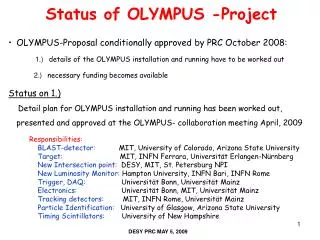
APS APRIL MEETING, 2010. “THE OLYMPUS LUMINOSITY MONITORS” Ozgur Ates Hampton University. *. * Supported by NSF grant No. 0855473. OLYMPUS Two Photon Exchange in Elastic Scattering Principle of The Experiment LUMINOSITY MONITORS Control of Systematics Technique.

E N D
APS APRIL MEETING, 2010 “THE OLYMPUS LUMINOSITY MONITORS” Ozgur Ates Hampton University * * Supported by NSF grant No. 0855473 • OLYMPUS Two Photon Exchange in Elastic Scattering Principle of The Experiment • LUMINOSITY MONITORS Control of Systematics Technique
Proton Form Factor Ratio JeffersonLab • All Rosenbluth data from SLAC and Jlab in agreement • Dramatic discrepancy between Rosenbluth and recoil polarization technique • Multi-photon exchange considered the best candidate to explain the dramatic discrepancy. Dramatic Discrepancy!
Elastice+-p/e--p Ratio Two-photon exchange theoretically suggested : Interference of one- and two-photon amplitudes Measure ratio of positron-proton toelectron-protonunpolarized elastic scattering to 1% Precision!! in stat.+sys.
Electrons/positrons (100mA) in multi-GeV storage ringDORIS at DESY, Hamburg, Germany • Unpolarized internal hydrogen target (buffer system) • Large acceptance detector for e-p in coincidenceBLAST detector from MIT-Bates available
Luminosity Monitors: Telescopes Luminosity monitors for LEPTON in coincidence withRecoil PROTON detected in the opposite sector, and vice versa. 2 tGEM telescopes, 1.2msr, 12o, R=187/237/287cm, dR=50cm, 3 tracking planes Forward telescopes PROTON LEPTON 12o LEPTON PROTON TOF
Control of Systematics Triple Super Ratio: Run the Exp. For the “4 different states” i= e- vs e+ j=toroidal magnet polarity(+-) Repeat cycle many times Ratio of luminosities Ratio of acceptances (phase space integrals) Ratio of counts • Forward-angle (high-epsilon, low-Q) elastic scattering (se+ = se-) means there is no two-photon exchange • Separately determine three super ratios • Left-right symmetry = Redundancy
Forward Elastic Luminosity Monitor • Forward angle electron/positron telescopes or trackers with good angular and vertex resolution • Coincidence with proton in BLAST • High rate capability • It will be built at Hampton University this year! • GEM Technology MIT prototype: Telescope of 3 Triple GEM prototypes (10 x 10 cm2) using TechEtch foils F. Simon et al., NIM A598 (2009) 432
Monte Carlo Studies by using Geant4 • Generated and reconstructed variables Theta, Phi, Momentum, Z(vertex) • Proton& Electron • Resolutions δZp, δTp, δPhp, δPp, δZe, δTe, δPhe, δPe • Residuals: Redundancy of variables / elastic scattering • 4 variables: Pe, Pp, Te, Tp • 3 constraints: 3 conservation equations4 – 3 = 1 (DEGREES OF FREEDOM) • TeTp: Te – Te(Tp) • TePe: Te – Te(Pe) • TePp: Te – Te(Pp) • Coplanarity: • PhePhp: Phe – Php – 180 • Common vertex:ZeZp: Ze – Zp
Resolution: generated-reconstructed 100micron, 50cm, LuMo+BLAST (Te=0-80 dg, Phe=+-15 dg) δZp δZe δTp δTe δPhe δPhp δPp δPe
Resolution: generated-reconstructed 100micron, 50cm, LuMo only (Te=6-13 dg, Phe=+-5 dg) δZp δZe δTp δTe δPhe δPhp δPe δPp
Design Parameters: Resolutions • Many configurations were simulated. • Varied intrinsic res. and distance between tracking planes. • 100 µm intrinsic res. and 50 cm gap between Gem1/2 and Gem2/3 show the optimum performance.
Conclusions • 10x10 cm2GEM detector size for active area at 12 degree. • Least distance of first element 187cm for clearance • The second should sit 237cm and third gem 287cm away from the target. • Elastic count rate still sufficient with 50cm gaps • 100 µmintrinsic resolutions of GEM’s meetthe experimental requirement.
Next Steps • Simulations of phase space integral(s), acceptance; expected counts • Study of systematic effects (beam offset, slope, width; etc.) on counts per bin • Simulation of backgrounds • Build and test the detectors by end of this year! • Implement in OLYMPUS in 2011, run in 2012