Download
1 / 1
10 likes | 149 Views
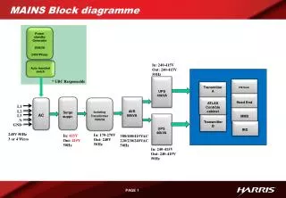
MAINS Block diagramme. Power standby Generator 200kVA 240V/Phase. L1. Auto transfert swich. L2. In: 240-415V Out: 240-415V 50Hz. L3. N. GND. * UBC Responsable. UPS 40kVA. PIE Rack. Transmitter A. Head End. AVR 80kVA. Surge suppr. ATLAS Contrôle cabinet. AC.

E N D
MAINS Block diagramme Power standby Generator 200kVA 240V/Phase L1 Auto transfert swich L2 In: 240-415V Out: 240-415V 50Hz L3 N GND * UBC Responsable UPS 40kVA PIE Rack Transmitter A Head End AVR 80kVA Surgesuppr. ATLAS Contrôle cabinet AC IsolatingTransformer 150kVA MMS Transmitter B UPS 40kVA IRD 240V 50Hz 3 or 4 Wires In: 170-270V Out: 240V 50Hz In: 415V Out: 415V 50Hz 380/400/415VAC 220/230/240VAC 50Hz In: 240-415V Out: 240-415V 50Hz