Advanced Concepts in Multi-Valued Logic Circuits and Applications in Memory Technology
This document explores the principles of multi-valued logic (MVL) circuits, focusing on logic systems that support more than two states. It covers the role of MVL in technologies like Intel flash memory, which utilizes multiple floating gate charge levels. Techniques for manipulating multi-output functions are detailed, including characteristic equations and positional cube notation (PCN). The document discusses the representation of variables in MVL, including the implications of different value sets and the application of logical operations. Examples of circuit minimization and merging techniques are also provided.

Advanced Concepts in Multi-Valued Logic Circuits and Applications in Memory Technology
E N D
Presentation Transcript
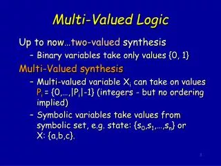
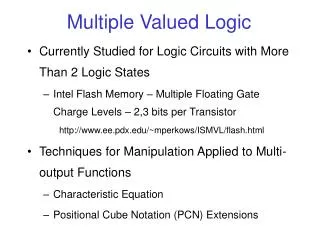
Multiple Valued Logic • Currently Studied for Logic Circuits with More Than 2 Logic States • Intel Flash Memory – Multiple Floating Gate Charge Levels – 2,3 bits per Transistor http://www.ee.pdx.edu/~mperkows/ISMVL/flash.html • Techniques for Manipulation Applied to Multi-output Functions • Characteristic Equation • Positional Cube Notation (PCN) Extensions
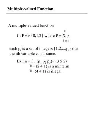
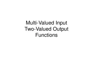
MVI Functions • Each Input can have Value in Set {0, 1, 2, ..., pi-1} • MVI Functions • X is p-valued variable • literal over X corresponds to subset of values of S {0, 1, ... , p-1} denoted by XS
MVL Literals • Each Variable can have Value in Set {0, 1, 2, ..., pi-1} • X is a p-valued variable • MVL Literal is Denoted asX{j}Wherejis the Logic Value • Empty Literal: X{} • Full Literal has Values S={0, 1, 2, …, p-1} X{0,1,…,p-1} Equivalent to Don’t Care
MVL Example • MVI Function with 2 Inputs X, Y • X is binary valued {0, 1} • Y is ternary valued {0, 1, 2} • n=2 pX=2 pY=3 • Function is TRUE if: • X=1 and Y= 0 or 1 • Y=2 • SOP form is: • F = X{1}Y{0,1} + X{0,1}Y{2} • Literal X{0,1} is Full, So it is Don’t Care • implicant is X{1} Y{0,1} • minterm is X{1}Y{0} • prime implicants are X{1} and Y{2} X F Y
Multi-output Binary Function x f0 y • Consider f1 z
Characteristic Equation Multi-output Binary Function W x F y z • Consider x f0 y f1 z
Characteristic Equation Sum of Minterms
PCN for MVL Functions • Binary Variables, {0,1}, Represented by 2-bit Fields • MV Variables, {0,1,…,p-1}, Represented by p-bit Fields • BV Don’t Care is 11 • MV Don’t Care is 111…1 • MV Literal or Cube is Denoted by C()
PCN for MVL Example • Positional Cube Corresponding to X{1} is C(X{1}) • Since Y{0,1,2} is Don’t Care
PCN for MVI-BO Example • View This as a SOP of MVI Function: • F is the Characteristic Equation
List Oriented Manipulation • Size of Literal = Cardinality of Logic Value Set x{0,2} size = 2 • Size of Implicant (Cube, Product Term) = Integer Product of Sizes of Literals in Cube • Size of Binary Minterm = 1 Implicant of Unit Size EXAMPLE f (x1,x2,x3,x4,x5,x6)
Logic Operations • Consider Implicants as Sets • Apply (, , , etc) • Apply Bitwise Product, Sum, Complement to PCN Representation • Bitwise Operations on Positional Cubes May Have Different Meaning than Corresponding Set Operations EXAMPLE Complement of Implicant Complement of Positional Cube
MVL Logical Operations • AND Operation – MIN - Set Intersection • OR Operation – MAX - Set Union • NOT Operation – Set Complement EXAMPLE
MVL Circuits MAX-gate MIN-gate
Cube Merging • Basic Operation – OR of Two Cubes • MVL Operation – MAX is Union of Two Cubes EXAMPLE = 1 {0,1} 0 1= 0 {0,1} 0 1 Merge and into = {0,1} {0,1}0 1
Minimization Example (cont) Sum of Minterms (Fig. 10.7 PLA Implementation) Merging • Merge 1st and 2nd • Merge 3rd and 4th • Merge 5th and 6th • Merge 7th and 8th
Minimization Example (cont) Multi-Output Function Using of Multi-Output Prime Implicants (Fig. 10.8 PLA Implementation)