Download
1 / 21
210 likes | 329 Views
This paper presents the development of a Finite Element Analysis Toolbox (FEAT) that facilitates the post-processing of graphite weight loss predictions in the UK nuclear industry. The tool models weight loss mechanisms, highlighting the effects on graphite density, strength, and effective moderation in reactors. Key features include mesh generation, contour plotting, and the ability to output data in MATLAB formats for analytical purposes. Future development aims to enhance user interaction through improved GUI functionality and broader usability across various FEAT mesh types.

E N D
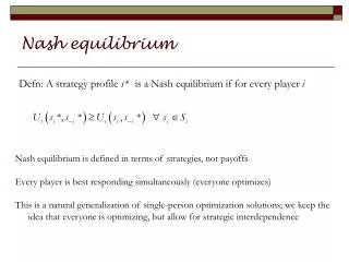
Development of a Finite Element Visualisation Tool for Post-Processing Graphite Weight loss Predictions Sukhbinder Singh, Frazer-Nash Consultancy
Contents Background to Graphite Background to FEAT Objective of Tool Mesh Generation Creating Contour Plots Example Meshes Future Development Summary
Graphite in the UK Nuclear Industry • Favourable neutron scattering cross-section at fast neutron energies • High thermal and electrical Conductivity • Use in Windscale piles • Civil use in Magnox and AGR fleet, new build reactors are all PWR’s
Graphite Weight loss Conditions in an AGR, are favourable for radiolytic oxidation of graphite via the interaction with a free radical Weight loss results in a reduction in graphite density leading to reduced strength and less effective moderation Loss of strength can lead to brick-cracking and potentially core distortion preventing control rod insertion during reactor transients, for example Weight loss mechanism is modelled using FEAT-Graphite
FEAT-Graphite • FEAT – Finite Element Analysis Toolbox • FEAT-DIFFUSE6 – Weight loss and Field Variables • FEAT-COILU – Stress Analysis and Properties
Finite Element Method • Model Brick as elements made up of nodes, edges and faces • Set boundary conditions • Model physics equations and calculate solution • Save results at certain time steps
Objective of Tool • Investigate the possibility of using MATLAB to view FEAT data and plot data in a way to minimise user interaction
Reading FRFs • Can save whole FRFs into MATLAB structure file • Select what to save • Save space on drive • View raw numbers in MATLAB and split into sections • Statistical analysis of variable • Possible to see how variable changes over time
Mesh Generation - Elements The brick is split into many different elements Elements can be of different shapes, only wedges and bricks are used to model the graphite bricks Type 54 - Brick Type 53 - Wedge
Mesh Generation – Brick Geometry Torness Mesh Hinkley Point B Mesh
Creating Contour Plots • Mapping distribution of the variable onto a plane on the brick • Main use of the tool • Constant height where nodes exist • Interpolation to any height
Slices through the height of the brick • Having been able to calculate how to slices at a constant height, next step was to do slices with varying heights:- • Azimuthal lines • Radial lines • User Defined lines
Further Development GUI Create software guidance for users Able to select nodes and follow variation of that node over time Volume and object selection Usable by any FEAT mesh – not just FEAT-Graphite Weight loss over the whole brick
Summary of Tool Capabilities Read in FRF and store data in a fashion which can be used to produce contour plots Recreate the mesh stored in the FRF Create contour plots of any variable across any height of the brick Create vertical slices across the brick at constant radius, angles and between user defined points
Thank you for listening – Any Questions? www.fnc.co.uk