Download
1 / 19
190 likes | 210 Views
This document discusses the conceptual design of the optical configuration for the Advanced Virgo Interferometer, including topics such as interferometer layout, recycling techniques, mirror specifications, thermal compensation, and interferometer sensing and control.

E N D
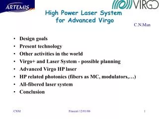
Advanced Virgo Optical Configuration - Conceptual Design - 09.10.2007 ILIAS-GW, Tübingen • Andreas Freise
The Conceptual Optical Configuration • Interferometer layout • Recycling techniques • Beam size and shape • Mirror (optics) specifications • Thermal compensation • Interferometer sensing and control A. Freise
3 km ~ 6 m 3 km The Interferometer Layout • Mirror positions as in Virgo • Arm cavities symmetric • Add a Signal Recycling mirror A. Freise
Signal Recycling Advantages: • Signal Recycling can significantly improve the sensitivity over a finite bandwidth • the detector response can be optimized on-line(compatible with Advanced LIGO, GEO HF, etc.) • The base of the vacuum tank for the Signal Recycling mirror is already installed • a new mirror has to be installed and controlled • resonance conditions for RF sidebands become more complex; this typically yields stronger noise couplings Disadvantages: A. Freise
Signal Recycling A. Freise
… the Baseline • Wide-band Resonant Sideband Extraction (RSE) • Arm cavity Finesse ~ 900 • Signal Recycling Mirror (for example) T=4% • Signal Recycling Cavity length similar to Power Recycling Cavity A. Freise
Mirror Specification Motivation: • A larger mass reduces the radiation pressure noise • Larger diameters (and thus larger beam sizes) reduce the thermal noise • High-finesse arm cavities require low losses (lower absorption, improved flatness) • Mirror size is limited by technical issues: size of coating and metrology equipment, maximum load of suspension systems • R+D underway to improve quality of substrates and coatings State of the art: A. Freise
… the Baseline • Mirror diameter: 35 cm • Mirror thickness: 20 cm • Mirror weight: 42 kg • Beam splitter diameter: 55 cm • Beam splitter thickness: 10 cm (very preliminary) A. Freise
Wedges • Baseline: wedges on all mirrors • This provides extra beams (optical read-out ports) • Removes the `etalon effect' A. Freise
Limited by the size of the coating on the beam splitter, e.g. for 30 cm coating: Beam Size and Shape • Maximize spot size (beam radius) on all arm cavity mirrors A. Freise
… the Baseline • TEM00 mode • Spot size ~ 3.5 cm to 6 cm on all core optics(BS, arm cavity mirrors, recycling mirrors) • Beam waist at center of arm cavity A. Freise
Thermal noise scales as: … the Alternative • Higher order Laguerre-Gauss mode (LG33 / LG55) A. Freise
… the Alternative • Higher order Laguerre-Gauss mode (LG33 / LG55) • Can reduce thermal noise significantly • Simplifies the requirements for thermal compensation • Can be used with the standard optics (spherical mirrors, lenses, etc.) • First investigations show that control signals are similar to those using TEM00 beams • R+D programme underway to investigate the efficient production of these modes and the noise couplings A. Freise
Transverse Mode Stability • Thermal effects due to absorption are already seen in current detectors and will increase due to larger power in Advanced detectors • Overlap of carrier light with RF sidebands is affected by thermal effects and alignment • Thermal compensation must be installed to mitigate the absorption effects • Passive stability of the optical cavities can be improved to increase the mode stability A. Freise
… the Baseline • Degenerate Recycling cavities • Thermal compensation on arm cavity input mirrors or compensation plates, following the R+D for and experience from Virgo+ A. Freise
… the Alternative • Non-degenerate recycling cavities • For example via telescopes inside the cavities • See R+D by LIGO A. Freise
Interferometer Sensing+Control • No conceptual design yet • Probably use DC detection for GW signal • Dedicated R+D programme (CALVA) for the use of auxiliary lasers for the lock acquisition A. Freise
Next steps • Start or continue dedicated R+D in new or improved optical techniques • Start trade-off analysis based on R+D results and experience from the commissioning of first generation detectors • Set final specification for long lead items • Engage in a system design of the entire (optical) instrument A. Freise
… end. A. Freise