Exercise Water pipe, Pump and Cooling Tower Selection
170 likes | 401 Views
Exercise Water pipe, Pump and Cooling Tower Selection. Cooling Load per floor is 40 kW, Heat load 16.5 kW 10 HP VRV unit gives >130% connection ratio 20 HP VRV unit gives 80-110% connection ratio, Depending on piping length 30 HP VRV unit gives <66% connection ratio 20 Hp unit is selected.

Exercise Water pipe, Pump and Cooling Tower Selection
E N D
Presentation Transcript
Exercise Water pipe, Pump and Cooling Tower Selection
Cooling Load per floor is 40 kW, Heat load 16.5 kW 10 HP VRV unit gives >130% connection ratio 20 HP VRV unit gives 80-110% connection ratio, Depending on piping length 30 HP VRV unit gives <66% connection ratio 20 Hp unit is selected Watercooled VRV Selection: VRV WII - Express
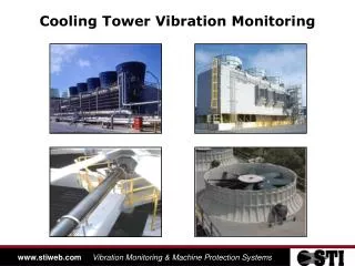
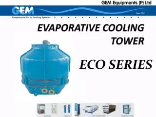
Cooling tower, evaporative cooler or dry cooler? Approach: 8°C, mild climate. Europe, small scale installation (No large water purification installation needed) Type: Evaporative fluid coolers Brand Baltimore: Type VXI Cooling unit Selection
Cooling mode: (VRV express) Total heating capacity available= 49.5W *4 Total Power Input at 98% connection ratio = 9.0 kW *4 Total rejected heat = 4 *(49.5+9.0)= 234 kW Total water flow (= max water flow )= 96 * 2* 4 = 768 l/min = 12.8 l/s Range= EWC – LWC = rejected heat / (4.186 x water flow) =177.6 / (4,186 x 12,8)= 4,37°C EWC= cooling tower entering water temperature= 30 + 4,4 = 34,4°C LWC= cooling tower leaving water temperature = 30 °C Approach = LWC – WBT = 30°C – 22°C = 8°C Calculations Evaporative Cooler Selection:
Selection Evaporator Determine the performance factor using the diagrams provided by Baltimore: Input: Range = 4.4 Approach = 8°C WBT = 22°C Output: Pf = 5
Heating mode: Total Heat capacity required= 63 kW *4 Total Power Input = 6 kW *4 Total injected heat = 4 *(63-6)= 228 kW Calculations Boiler Capacity:
Each VRV has as design waterflow 96 l/min per 10 Hp unit. Horizontal piping to indoor units: 2 x 96 l/min = 192 l/min Vertical parts: Different sections A, B, C, D Secton A: Only 1 20 HP unit: 192 l/min (=3,2l/s) Section B: 2x 20 HP unit : 384 l/min (=6,4l/s) Section C: 3x 20 HP unit, 576 l/min (=9,6l/s) Section D: 1x 10 HP Sub-unit, 96l/min (=1,6l/s) Section E: 4x 20 HP unit: 768 l/min (=12,8l/s) Reverse Return Distriubution * * C A E D B B C A Water piping: water flow rates
Piping diameters B D C A E
Using Friction loss graph: * * C A E D -0.21 B B +3 +0.15 C A 3m C+B+C+horizontal: 3m A+B+C+horizontal Linear Head Loss Opposite effect of joints Comparable results! Reference Path: Take worse case:
Local friction losses: For 1 water route: 3 branches “Straight Trough” 2 x “Trough Branch” connection on main line (2 for each 10 HP unit, speed ) 2 x “Trough Branch” Joint on indoor piping 2x 3 elbow joints on indoor piping Straight line friction losses: 4 x 3 m vertical piping, 2 x 3 m indoor piping * * C A E D B B C A Water Pipe Design: Local Head losses
T joints “Straight Trough” E to C C to B B to A . * * C A E D B B C A Local Head loss: Blue path vs Red path • T joint “Trough Branch” • A to E • B to A • A to C • E to C • C to B • C to E -1 -0. 11 +0.02 + 1.7 +1 4.2 + 5.7 +0.29 Total: +0.20
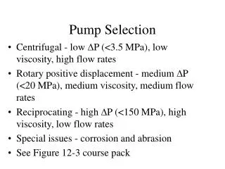
Piping design – pump selection properties H = Ha + Hf + Ht + Hk Ht = Linear Head loss = 1.55 mH2O Ha = Actual head (m H2O) = 0 Ht = Partial friction loss = 2,23 m H2O Hk = Internal friction loss = 2,7 mH2O 1 x 1 VRV 10 HP unit, at 96 l/min Hk2 = Given, 5 mH2O Total head loss= 11,48 mH2O at a flow rate of 768 l/min 46 m3/hr +0.14 mH2O