Download
1 / 45
480 likes | 1.06k Views
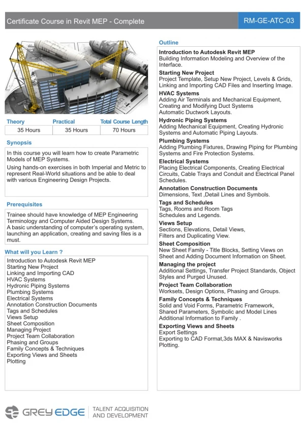
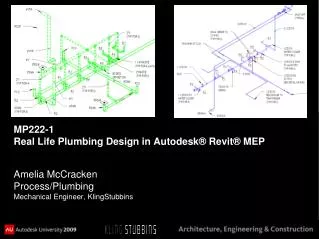
MP222-1 Real Life Plumbing Design in Autodesk® Revit® MEP . Amelia McCracken Process/Plumbing Mechanical Engineer, KlingStubbins. About the Speaker. Joined KlingStubbins in 2006 after earning Bachelor’s degrees in Mechanical Engineering Engineering from Drexel University.

E N D
MP222-1 Real Life Plumbing Design in Autodesk® Revit® MEP Amelia McCracken Process/Plumbing Mechanical Engineer, KlingStubbins
About the Speaker • Joined KlingStubbins in 2006 after earning Bachelor’s degrees in Mechanical Engineering Engineering from Drexel University. • Contributed to many of the firm’s large commercial and laboratory projects. • Proficient in software programs ranging from manufacturing 3D applications to 2D applications. • Contact Information: amccracken@klingstubbins.com
About the Firm Architecture Engineering Interiors Planning Philadelphia, PA Cambridge, MA Raleigh, NC San Francisco, CA Washington, DC Beijing, China
Class Description • Insight regarding the advantages of using a 3D software program to not only aid in coordination but save design drafting time. • In-depth look at how to make plumbing design in Revit MEP work for projects by developing design guidelines. • The constant CATCH 22 with all new software is to know what you can and cannot utilize to save time. • This class will benefit Plumbing Design Engineers who are looking to make Revit® MEP work for their projects. • Attendees should have plumbing design backgrounds and a general usage knowledge regarding Revit MEP Software.
Main objective of this Course: To SHARE my KNOWLEDGE & EXPERIENCE of the program to “get a package out the door” In the End we can not get caught up in the ooooo’s and aaahhh’s of the program because our boss and the Clients we work for, want to see a finished project on the table… … and that finished project better look the same way to contractors as it did with 2D programs… (if not better!)…
Specific Class Objectives • Using Filters to depict classic design standards for piping and equipment • Pipe types and how to utilize them to improve time it takes to design. • Schematic 2D plans v. 3D on plans • 3D Isometrics as plumbing risers • What to model, what not to model to match 2D plan
Resources: There are numerous websites and blogs created by Autodesk affiliates that offer useful information regarding Plumbing in Revit MEP such as: http://inside-the-system.typepad.com/my_weblog/ (AutoDesk Numerous Contributors – Inside the System) http://revitbeginners.blogspot.com/
How I came to know, what I know… (through frustration!!) • First Project - Used Revit® MEP 2008 and then upgraded to Revit MEP 2009 and the project was completed in January 2009, in construction now, Governement Project. • Second Project - Used Revit® MEP 2008 and then upgraded to Revit® MEP 2009 and the project was completed in October 2008, Autodesk Headquarters in Waltham, Ma tenant fit-outs. • Third Project – Miscellaneous Projects that started in Revit® MEP 2009 and then upgraded to Revit® MEP 2010, Penn State and another Government Project.
Lessons Learned • Start with Basic Training • Then Basic Piping Drafting… • Then Model Structure & Trouble shooting simple problems • Then designing and realizing you have to • THINK OUTSIDE THE BOX • Mistakes are going to happen • Learning from them is key and sharing the experience. • Learning Curve factor is going to happen • But future production will benefit from this.
General Overview of Project setup • Organization of the model: • Cadd Coordinator, BIM specialist, DDC (Digital Design Coordinator), etc. • Plumbing Design Template • Goals/Final results from the Model • Isometric Diagrams used as Risers • Coordination Conflict Resolution • Project Timeline • Sufficient time given for Deadlines
Systems and using Filters for organization • Go to Visibility Graphics or Shortcut – VV • Click on Filters
Filters • Example of using Filters to get drawing graphics needed for documentation
Filters • Use for all Systems • Line Style to match Industry Standard • Piping representation looks better in: • Sheet drawings look the same as 2D software output For simplicity Filters can be related to ‘Levels’ or ‘Layers’ in a Standard 2D software program… except these ‘Levels’/’Layers’ or Filters are intelligent because they are related to Systems.
Filters • Examples: Vent, DHWR, DCW, DHW, etc.
Creating Systems to create Filters • Example: Storm – Roof Drain • Select the connector • Go to Element Properties of the connector
Systems – Setting them up – Templates • Change the System Type to ‘Other’ • Give the Connection Description a name, use ‘ST’ for Storm • Then Load the Family into the Project • Place the Family where necessary
Systems – Setting them up – Templates Select the Roof Drain Select Edit System
Systems – Setting them up – Templates Select Add to System System Name: Change to ‘ST’ Finish Editing System
Systems – Setting them up – Templates Now check Visibility Graphics (VV) to make sure the Filter is on. System Name: Change to ‘ST’
Systems – Setting them up – Templates Now System and Piping are related and visually displayed through the filter to give the designer the same reassurance as 2D drawings. Smart Tags can now be applied that related to the System ‘ST’
Systems – Filters – Seems so easy, right? Using Piping Names to make Filters Using Comments to make Filters NO!! Backdoor ways to make it work…
Systems – Filters • Systems with Issues would be: • Natural Gas (NG) • Storm (ST) • Etc.
Systems – Filters Storm (ST)
Systems – Filters Storm (ST)
Systems/Filters - Recap • Learned from Mistakes to find the right way. • In the end it still worked out and the project went out a success. • Initial projects used to the ‘back door’ method because they were small. Large projects would have been a problem. • New Systems need to be created for those not incorporated in current software. • Filters help bring the 3D model back to a 2D drawing mindset.
Filters/Systems – 3D Views as Isometric Risers Sanitary Waste and Vent
Filters/Systems – 3D Views as Isometric Risers • Lessons Learned: • Vent is directly on top of Sanitary • P-Traps did not look like industry ‘Standard’
Filters/Systems – 3D Views as Isometric Risers • Lessons Learned: • P-Traps did not look like industry ‘Standard’ for the floor drains.
Filters/Systems – 3D Views as Isometric Risers • Lessons Learned: • Dashed Venting with Double Line piping can be confusing. • Tagging/Text is not ‘Smart’ in 3D views. • Flow arrows are not ‘Smart’ in 3D views. • Flow Diagram looks better without showing Fixtures.
Filters/Systems – 3D Views as Isometric Risers Domestic Hot and Cold Water
Filters/Systems – 3D Views as Isometric Risers • Lessons Learned: • Modeling DCW to Water Closets meaning DCW line can not be shown directly down the middle of chase.
Filters/Systems – 3D Views as Isometric Risers • Lessons Learned: • Tagging/Text is not ‘Smart’ in 3D views. • Flow arrows are not ‘Smart’ in 3D views. • Flow Diagram looks better without showing Fixtures.
Filters/Systems – 3D Views as Isometric Risers Isometric in PDF submission drawing.
Filters/Systems – 3D Views as Isometric Risers - Recap • This is where Time Saving comes into play. • Low-Rise building are perfect for using Isometrics as Riser • High-Rise buildings require more attention when using Isometrics but it can be done. • Numerous floors need to be cut into sections.
What to Model, What Not to Model • What I found to be Helpful: • Extras • Sections – Not normally necessary for plumbing documentation. • Families • It is not necessary to have all Families modeled. If what matters ends up on 2D plans. • We didn’t feel that we needed chair carriers, showers, etc.
What to Model, What Not to Model • Extras • Sections can be created with ease if requested by a client. • Also a great tool for designing. • Not necessarily something to submit on a document.
Schematic 2D plans vs. 3D on plans • Still get the same results as 2D software
Schematic 2D plans vs. 3D on plans • Kitchen with Grease Interceptor
Schematic 2D plans vs. 3D on plans • 2D plan • Double line piping • Revision Clouds and tags – all intelligent
Schematic 2D plans vs. 3D on plans • One Software Issue for drawings – Presentation of PDFs • Walls appear to block out piping. • Autodesk was made aware of this. It is eliminated if raster is used instead of vector to PDF.
Bringing 2D Details into Revit® MEP Existing library of 2D CADD information. Process to bring 2D CADD details to make the Line work and text be Revit Line work and text Extensively importing details can hinder the model… therefore have a plan.
Moving Forward – Total Recap • Main Goal – Share my Knowledge • Do not get caught up in Software capabilities and inabilities • Using 3D view as Isometric Riser • Using Systems and Filters to organize and increase productivity • Projects can be done in the same allotted time using Revit®MEP as long a decent foundation has been established or can be supported.
Moving Forward – Total Recap Current Challenges: Using single-line pipe work instead of double line. The software will not ‘break piping’ as normally done manually in 2D software. Numerous items need to ‘Hide in View’. CADD departments to help with details being converted to 2D Revit® MEP Issue with text not being ‘Smart’ in the 3D Isometric Risers. Main suggestion is to have a plan and do not just use Revit®MEP for coordination but be willing to supports areas of inadequacy. Ongoing Benefits: • Using Isometrics as 3D Risers Diagrams. • Smart tagging. • Intelligent piping Systems. • Intelligent Filters • Coordination is complete while designing and can easily be checked.
Questions? amccracken@klingstubbins.com