How to Program an IC Chip
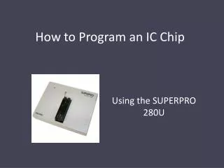
How to Program an IC Chip. Using the SUPERPRO 280U. The instructions vary slightly between different chips. Follow red instructions if you are using the 2532 or the 2532A. Follow green instructions if you are using the 27C64. Follow blue instructions if you are using the 28C64.

How to Program an IC Chip
E N D
Presentation Transcript
How to Program an IC Chip Using the SUPERPRO 280U
The instructions vary slightly between different chips • Follow red instructions if you are using the 2532 or the 2532A. • Follow green instructions if you are using the 27C64. • Follow blue instructions if you are using the 28C64. • Follow purple instructions if you are using the GAL16V8. • Follow white instructions for all chips.
Switch on power to the unit and wait for the LED to turn green • Open the Superpro program on the desktop • Choose device you wish to program by clicking on device icon
Select appropriate manufacturer and device name • Under Manufacturer click TI , then TAB over to Device and select TMS2532 or the TMS2532A depending on your chip. • Under Manufacturer click AMD, then TAB over to Device and select AM27C64 . • Under Manufacturer click Atmel, then TAB over to Device and select AT28C64B . • Under Manufacturer click Lattice , then TAB over to Device and select GAL16V8.
Program should indicate that it is ready • Place chip in the programmer in the ZIF socket • Pull lever to open slots • Place in programmer at the bottom of the slots with pin 1 pointing towards lever • Close slots by moving lever to original position
NOTE: This step only needed if you are using a UV erasable device (i.e. 2532A or 27C64). • Check that EPROM has been erased • Click Blank_Check and await verification • Click read button • Examine buffer to ensure that all points in memory are FF
Load your program into the buffer • Press the load button. • Select the *.hex or *.jed file you wish to load into the chip
The File Type window will appear Choose the appropriate file address but leave the buffer address unchanged Set the File address to F000 Set the File address to E000 Set the File address to E000 Not needed for the GAL16V8.
Verify your program is in the buffer • Press the buffer button • Examine hex code to ensure it matches your program • If you are running a standalone program, ensure that Reset/IRQ vectors are set
Program your chip • Press the Program button • LED on device should turn orange. • LED will turn green again once programming is complete • If LED turns red then there has been an error and you may need to re-program the chip. This is usually due to the chip not making a complete connection within the programmer socket. NOTE: LED will stay red until the next successful operation is complete • Once complete, press the Verify button to ensure that the program has been loaded successfully • NOTE: UV erasable devices take much longer to program then electrically erasable devices. Remember to turn off the programmer when you are done!!!!