Download
1 / 22
220 likes | 253 Views
The Status of Maxlab and MAX IV RF Systems. Lars Malmgren On behalf of the Max-lab RF team. Outline. MAX IV overview Status at construction site Linac Main cavity Higher harmonic cavity Digital low level RF. MAX IV. MAX IV overview. Start 3.5 GeV Linac. Short Pulse Facility.

E N D
The Status of Maxlab and MAX IV RF Systems Lars Malmgren On behalf of the Max-lab RF team ESLS RF Grenoble, October 5-6, 2011. Lars Malmgren
Outline • MAX IV overview • Status at construction site • Linac • Main cavity • Higher harmonic cavity • Digital low level RF ESLS RF Grenoble, October 5-6, 2011. Lars Malmgren
MAX IV ESLS RF Grenoble, October 5-6, 2011. Lars Malmgren
MAX IV overview Start 3.5 GeV Linac Short Pulse Facility 1.5 GeV ring 3 GeV ring ESLS RF Grenoble, October 5-6, 2011. Lars Malmgren
Construction site At the MAX IV Site. In Accelerator Pit at the Electron Gun Position towards Beamdump. Photo: Annika Nyberg, MAX IV Laboratory, 2011-09-28. ESLS RF Grenoble, October 5-6, 2011. Lars Malmgren
Linac • Total length 275 m • 18 S-band RF units (klystron+ solid state modulator) supplied by Scandinova, Uppsala, Sweden. Contract signed 11/8/2010. First unit delivered in mid December 2011. • Toshiba klystron E37310 • 18 acceleration units, supplied by RI Research Instruments GmbH, Bergisch Gladbach, Germany, consisting of SLED (18 units), power devider (20 units) and Linac sections (39). They are delivered conditioned. Contract signed 15/07/2010. Delivery of the first unit in March 2012. • First RF unit feeds two guns and one linac structure. The rest, except the last two are feeding two linac structures each. The last two feeds four linac structures. • Installation is expected to begin March 2013 ESLS RF Grenoble, October 5-6, 2011. Lars Malmgren
RF unit • S-band RF Unit parameters MAX IV Laboratory, 11.06.14. D. Kumbaro ESLS RF Grenoble, October 5-6, 2011. Lars Malmgren
Gun test stand • Test of high brightness gun • Test of linac diagnostics: • YAG screens • BPM ESLS RF Grenoble, October 5-6, 2011. Lars Malmgren
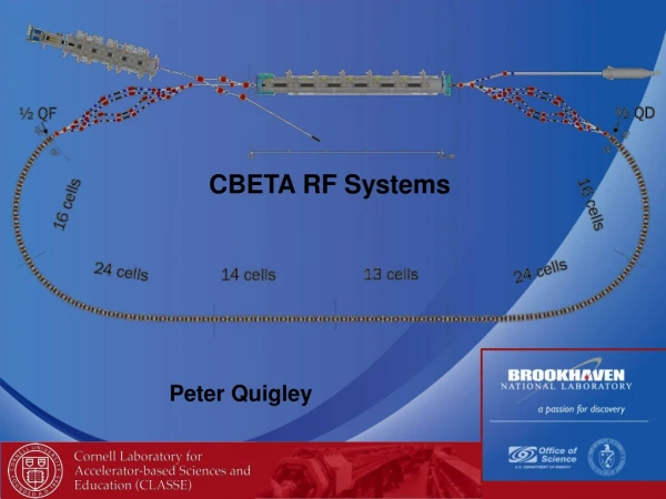
3 GeV and 1.5 GeV RF Stations Block diagram of the 3 GeV RF system • Commercial 60 kW FM transmitter can be used in both the 3 and 1.5 GeV rings. • In the 3 GeV ring each RF station consists of two combined transmitters • In the 1.5 GeV ring an identical single 60 kW transmitter would constitute the RF station • It is a advantage with a modular RF system for the MAX IV rings. • Circulators will be used in both rings to isolate the cavity from the transmitters ESLS RF Grenoble, October 5-6, 2011. Lars Malmgren
Procurement main cavities & couplers • We have ordered 8 main cavities from Research Instruments (RI). Delivery before Christmas! • We have order 8 input power couplers of DORIS type from RI. Should safely handle 120 kW. Delivery Feb 2012. • We will need 16 HOM couplers. The intention is to give a design idea to RI, who will fabricate an in-vacuum prototype for tests. Put on ice! ESLS RF Grenoble, October 5-6, 2011. Lars Malmgren
Procurement Landau cavities ESLS RF Grenoble, October 5-6, 2011. Lars Malmgren • A contract is signed stating an agreement between MAX and RI of ”common activities” in order to reduce a given ceiling price for 6 Landau cavities. This includes finalizing the MAX-lab prototype Landau. Prototype now in house!
Landau cavity prototype f = 300 MHz Theory: Rsh = 5.8 Mohm Q = 21800 Å. Andersson ESLS RF Grenoble, October 5-6, 2011. Lars Malmgren
Landau cavity design The prototype is ready f = 300 MHz Practice: Rsh = 5.6 Mohm Q = 21000 Mechanical design; Elsayed Elafifi, MAX-lab ESLS RF Grenoble, October 5-6, 2011. Lars Malmgren
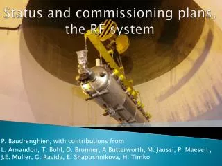
Assembly of central rods • Assembly of the water cooled rods with capacitor plates. Two with fixtures for EB welding mounted. ESLS RF Grenoble, October 5-6, 2011. Lars Malmgren
Backplate Back plate after EB welding and turning. ESLS RF Grenoble, October 5-6, 2011. Lars Malmgren
Turning the inside of the cavity The shell is made of two halves that are EB welded together. This picture shows the final cut taken in the lath. ESLS RF Grenoble, October 5-6, 2011. Lars Malmgren
Landau cavity with tuning mechanism Extra plunger for safe MAX-III operation. The prototype is ready to be installed in Max III ESLS RF Grenoble, October 5-6, 2011. Lars Malmgren
Digital Low Level RF • A digital low level RF(DLLRF), based on the ALBA LLRF, has been developed by Angela Salom and Antonio Milan, ALBA in corporation with Max-lab • It controls the amplitude and phase of cavity voltage and resonance frequency (Tuning) • Each DLLRF controls two RF stations • 10 RF diagnostic signals per RF station ESLS RF Grenoble, October 5-6, 2011. Lars Malmgren
The DLLRF hardware • FPGA from Lyrtech, VHS ADAC-4 • cPCI format • 8 ADCs 125 MHz 14 bits • 8 DACs 125MHz 14 bits • Virtex 4 • 128 Mbytes RAM • 16 ADCs and FPGA for Diagnostics ESLS RF Grenoble, October 5-6, 2011. Lars Malmgren
High power tests with beam High power tests with beam was performed at 19 of September on the Max III storage ring. The injection energy was 400 MeV which was ramped to 700 MeV. The ramping was done with all feedback loops running and the beam survived. We will continue the testing when there is a possibility. Unfortunately there is not much time available due to user operation. ESLS RF Grenoble, October 5-6, 2011. Lars Malmgren
Diagnostics Fast Diagnostics • Signals acquired at 5MHz rate • Signals stored in a circular buffer of 128MBytes (equivalent to 0.5s of operation) • Used for post mortem analysis and transient studies Slow diagnostics • Signals acquired at 0.3Hz rate • Archiving for historical purposes • Slow trend analysis Control System in Tango ESLS RF Grenoble, October 5-6, 2011. Lars Malmgren
Thanks for your attentionQuestions? ESLS RF Grenoble, October 5-6, 2011. Lars Malmgren