Download
1 / 62
2.38k likes | 5.9k Views
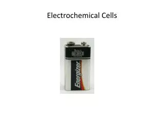
Unit-IV. Electrochemical Sensors. By Dr.K.Venkateswara Rao Associate professor of Nanotechnology JNT University Hyderabad. Potentiometric Sensors.

E N D
Unit-IV Electrochemical Sensors By Dr.K.Venkateswara Rao Associate professor of Nanotechnology JNT University Hyderabad
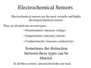
Potentiometric Sensors A potentiometric sensor is a type of chemical sensor that may be used to determine the analytical solution of some components of the analyte gas or solution . These sensors measure the electrical potential of an electrode when no voltage is present Principle: The signal is measured as the potential difference (voltage) between the working electrode and the reference electrode. The working electrode's potential must depend on the concentration of the analyte in the gas or solution phase. The reference electrode is needed to provide a defined reference potential
The experimental set-up is simple. As reference electrodes, those of the second kind are useful. They are created by a combination of a metal/metal ion electrode and a stock of a sparingly soluble salt of the participating metal. Among the practical examples is the silver/silver chloride electrode with a salt bridge of potassium chloride solution. The instrument for potential measurement must be characterized by a very high input resistance. Experimental set-up for potentiometry So-called pH meters are well suited for this purpose since they commonly have input resistances in the gigaohm range.
With the advent of the sensor age, efforts were launched to miniaturize sensors and to mass produce them. Simultaneously, a tendency arose to apply the term sensor also for well-known traditional potentiometric probes. It seems better, however, to restrict the term sensor exclusively to devices characterized by miniature dimensions and by widespread availability. Nevertheless, it is useful to start with classical electrode forms when discussing potentiometric sensors. Classical potentiometric electrodes differ from potentiometric sensors only in their geometric dimensions.
Nernst’s equation is the basis of all potentiometric measurements. The common form of this equation is that given in below Equation for a working temperature of 25◦C. Equation describes activity rather than concentration. Potentiometric measurements always result in activity values. The number Zi is identical to the charge of the ion studied. The sign of the concentration-dependent term is positive for cations and negative for anions. A closer look at the equation shows that a concentration change by a factor of 10 should result in a potential variation of ca. 60mV for single charged ions but 30mV for double charged ions. Consequently, the concentration of single charged ions can be determined with higher precision. Eθ’ is not identical to the standard potential Eθ. Itis a constant which depends mainly on the reference electrode used and mustbe determined empirically for the actual set-up
The thermodynamic deduction of the Nernst equation given in ignores the fact that the value measured between working and reference electrodes is composed of numerous interface voltage values, the Galvani potential differences gi. (Figure) tries to demonstrate how a measurable voltage (EMK) could arise at a copper/copper ion working electrode and a hydrogen reference electrode. The ordinate distances drawn to symbolize g values are hypothetical, of course Potential difference measured between working and reference electrodes interpreted as sum of all Galvani potential values at each interfaces gi, and alternatively as inner potential ifference between outer phases φ(I) and φ(I’)
Classification of sensors Potentiometric solid state gas sensors have been generally classified into three broad groups • Type I sensors have an electrolyte containing mobile ions of the chemical species in the gas phase that it is monitoring. The commercial product, YSZ oxygen sensor, is an example of type I. • Type II sensors do not have mobile ions of the chemical species to be sensed, but an ion related to the target gas can diffuse in the solid electrolyte to allow equilibration with the atmosphere. Therefore, type I and type II sensors have the same design with gas electrodes combined with metal and an electrolyte where oxidized or reduced ions can be electrochemically equilibrated through the electrochemical cell. In the third type of electrochemical sensor, auxiliary phases are added to the electrodes to enhance the selectivity and stability. • Type III sensors make the electrode concept even more confusing. With respect to the design of a solid state sensor, the auxiliary phase looks as part of the electrode. But it cannot be an electrode because auxiliary phase materials are not generally good electrical conductor. In spite of this confusion, type III design offers more feasibility in terms of designing various sensors with different auxiliary materials and electrolytes.
Selectivity of Potentiometric Sensor • Selectivity is one of the most important advantages of potentiometric sensors. The ideal case would be the specific sensor which responds to only one single type of ion. • This ideal cannot be reached in practice, but some types of sensor approximate it. Commonly, for every analyte a certain number of disturbing substances exist which cause interferences. • The interfering ion ‘simulates’ the presence of a certain sample ion concentration. This distortion is not constant but affects lower sample concentrations, though to a lesser extent than it affects higher concentration values • To overcome this problem, different attempts have been described. The best known approach is the Nikolskij equation (Nikolskij– Eisenman equation), given below. This equation considers the sample ion i, which is in competition with the interfering ion j. The extent of interference is expressed in terms of the selectivity coefficient Kij. The numbers zi and zj are the charge numbers of sample and interfering ions, respectively.
The selectivity coefficient expresses the ratio of sensitivities of interfering vs. sample ion. As an example, the value Kij = 10−2 means that the interferent must be present in a 100-fold excess compared to the sample to bring about an equal effect at the sensor: The above equation proves that the effect of interference decreases with increasing sample activity ai. The selectivity coefficient can only give some indication of a possible distortion.
Ion-Selective Electrodes As mentioned in a previous chapter, the art of manufacturing ion-selective electrodes (ISEs) consists in searching for the proper method to prepare the sensor surface in such a way that a Galvani potential difference results which should depend selectively on the activity of only one type of ion, if possible. The best option would be a specific electrode, but at the very least it should be selective IESs are classified into two main groups, depending on whether the interface in contact with the sample solution is a solid surface or a liquid surface. The resulting groups are solid-membrane electrodes and liquid-membrane electrodes.The term ‘membrane’ in this case does not always mean a thin film as usual, but can be a compact body.
Among the IESs, the well-known glass electrode occupies a place of particular importance, more so than any other ISE, and it can be assigned to the group of solid-membrane electrodes as well as to that with a liquid membrane. Galvanic cells can be set up with solid electrolytes rather than electrolytic solutions. Such a cell is the basis for a well-known potentiometric gas sensor, the lambda probe. The latter is designed to determine the oxygen content of combustion gases, e.g. in motor vehicles. The lambda probe can operate in two different modes, either potentiometrically or amperometrically.
The Ion-Selective Field Effect Transistor (ISFET) An ISFET is an ion-sensitive field effect transistor used for measuring ion concentrations in solution; when the ion concentration (such as H+, see pH scale) changes, the current through the transistor will change accordingly. Here, the solution is used as the gate electrode. A voltage between substrate and oxide surfaces arises due to an ion sheath.. For mass production of this sensor type, nearly all the highly developed technological arsenal of microelectronics could be used. On the other hand, all the achievements of potentiometry with ISEs also became usable for ISFET sensors. ISE with MOSFET and low impedance connection to measuring instrument (left). Measuring set-up with ISFET (right)
ISFET structure (simplified) The above ISFET structure is identical to that of the MOSFET. Commonly, two n-type zones are incorporated in a substrate of p-doped silicon. The substrate is covered by an insulating layer formed normally by silicon dioxide. Sometimes silicon nitride Si3N4 is used. A component made with such a composition would more accurately be called not MOSFET, but IGFET (isolated gate FET). Both oxides and nitrides are good insulators. The metallic gate layer is plated on top of the insulating layer.
Finally, the ion-selective film is applied on top of the gate. The emf appearing between the reference electrode in solution and ion-selective membrane appears as a voltage between the gate and source electrodes of the MOSFET, as shown in figure. This gate-sourcevoltage acts as an input voltage of the amplifier circuit and will bring about a linear current increase, which is measurable at the output of the circuit. Alternatively, an amplifier circuit with constant drain current can be used. All the ion-selective membrane materials mentioned in connection with solid- and liquid-membrane ISEs can be used with ISFETs. The most common are pH-sensitive ISFETs. They do not suffer from the traditional drawbacks of glass electrodes, namely high price, fragility and extremely high impedance. Even the insulation layers of SiO2 and Si3N4 exhibit some pH sensitivity. More common pH-sensitive layers are liquid membranes (polymers with solvent) containing ion exchangers, e.g. amines attached with a hydrophobic alkyl chain at the opposite end. pH-sensitive glass has also been tested, in an adaptation of enamel electrodes. pH-sensitive ISFETs are commercially available, but they are still unable to replace the classic glass electrode.
Two problems have accompanied the development of the ISFET from the very beginning. • The first one is the problem of direct contact for making contact with the sensitive membrane, which is inherent in ISEs. • The second problem is encapsulation of the humidity-sensitive regions of the MOSFETsubstrate in such a way that only the gate (including the ion-selective layer) is exposed to solution. The technological progress achieved by the introduction of ISFETs is somewhat diminished by the fact that an external reference electrode is still necessary for measurement.
An alternative solution, where silicon technology is used throughout, is depicted in figure(Smith and Scott 1986). In this example, the basis is a pH-sensitive ISFET on an n-type silicon chip. A groove is formed by ‘anisotropic etching’. The following technological steps (formation of p-doped zones by diffusion, generation of an isolating nitride film, metallizing with aluminium etc.) result in the formation of a MOS structure. Finally, by etching with hydrofluoric acid, a porous silicon layer is generated inside the groove. The latter acts as a diaphragm, which establishes the liquid–liquid junction to the AgCl pellet added later. The described process retains some advantages of microelectronics technology but suffers from some additional elaborate steps. ISFET in silicon technology with integrated microreference electrode.
Measurement with Potentiometric Sensors Measuring Instruments To ensure accurate measurement, instruments which work with ISEs must have a high input impedance. As a rule of thumb, their input resistance should be ca. 100 times higher than the internal resistance of the cell containing the ISE. Since several ISEs (e.g. the glass electrode) have resistances in the range of megaohms, a good pH meter should have at least an input resistance of gigaohms. Even low-cost pocket pH meters fulfil this requirement today. The lead from the working electrode to the meter must be shielded carefully to avoid distortion by external electric fields of the surroundings. With ISFETs, measurement is much easier than with ISEs. There are two ways to design the measuring circuit.
In the circuit with a constant gate voltage, the drain current ID of the ISFET is a function of the gate voltage UG according to ID = k · UG. The current follower shown in Fig. 7.16 sets the potential of the source terminal virtually to zero (mass potential) and outputs a voltage proportional to the gate voltage. In the circuit with a constant drain current, the voltage value between the reference electrode and the ion-selective membrane appears unchanged at the output, but with low impedance. This circuit is most common with ISFET applications. In this circuit, all the details of a sensor signal are followed and may be manipulated by microcomputers. Connection of ISFETs with measuring instruments. Left: constant gate voltage, Right: constant drain current
Experimental Conditions Results of potentiometric measurements are always activity values. For chemical analysis, however, concentration values are desirable. In order to obtain a clear relationship between the concentration and the measured signal, the activity coefficient should be kept constant. This requirement can be fulfilled by establishing a high value of ionic strength I. The actual value of ionic strength determines activity coefficients of all ion types present in solution. The higher it is, the more stable it is against variation by addition of foreign components. Independent of ionic strength, the pH should be kept constant during measurement. Also, the temperature should not vary too much. The temperature dependence of the Nernst factor will cause an error of 2% per Kelvin for single-charged ions. A common practice is to mix a metered volume of the sample solution with a known amount of a buffer solution which also sets the ionic strength at a high value.
Such buffer solutions are commercially available under the name TISAB (total ionic strength adjustment buffer). Commonly they also contain some antioxidant (e.g. ascorbic acid) designed to exclude negative effects of atmospheric oxygen. Useful compositions can be found in application notes of electrode suppliers. Here, as an example, a TISAB suitable for fluoride determination by means of a fluoride-sensitive electrode is used. The buffer is prepared starting with a solution of 1M sodium chloride, 1M acetic acid and 1mM citric acid. By adding solid sodium hydroxide, the pH is adjusted to a value of 5.5. This pH is stabilized due to the function of the acetic acid/acetate buffer system. The value is optimum for fluoride determination. A higher pH, according to strong alkaline reaction, would cause a too strong interference of OH− ions.
Calibration The relation between measured value E and the logarithm of concentration c is established by calibration. This procedure is necessary since every sensor has its own characteristics that must be considered in order to get precise analytical results. Calibration can be done either by plotting a calibration graph or alternatively by the standard addition technique. Calibration graphs are produced by performing a second experiment following the literal measurement. In this second experiment, a series of measurements is done with known concentrations of the substance to be analysed. All conditions should be as close as possible to the sample analysis. The graph E = f (log c) is utilized as a reference to determine the concentration cx which belongs to the measured value EM. If potentiometric calibration graphs are not linear, then a non-Nernstian behaviour is perceptible, which means that the electrode may produce inaccurate results.
This figure depicts the typical shape of calibration graphs for potentiometric sensors. At the upper limit, i.e. at very high analyte concentrations, the electrode does not obey the Nernst law. The lower limit of solid-membrane electrodes is marked commonly by their own solubility. The electrode itself generates the concentration indicated. This threshold concentration is increased if interfering ions are present. According to the Nikolskij equation, depending on the selectivity coefficient Kij, above a specific value of interferent concentration cj only the interfering ion generates a signal. Calibration graphs suffer from the disadvantage that they must be recorded in a separate experiment, outside the sample solution. In many cases, unknowncomponents in the sample solution will affect the result. Even if efforts aremade to make the reference solution similar to the sample solution, this canbe successful only if all its constituents are known. Otherwise, some error willresult. Typical calibration graphs for ionselective ions. 1 without interfering ion; 2 and 3 with interferent.
Determining Selectivity Coefficient The selectivity coefficient can be determined by means of a simple method which has been recommended by IUPAC. First, a solution of the interfering ion j is prepared. The concentration is chosen to induce a marked signal. Next, consecutive additions of the sample ion are made in such a way that the ionic strength is not changed. It seems that the intererent solution is ‘titrated’ with the sample ion. The resulting curve is depicted schematically in below Fig At the intercept of both extrapolated straight lines, the corresponding signal E(intercept) might be caused by the interferent activity aj(intercept) as well as by the sample ion activity ai(intercept). According to the Nikolskij equation,the following condition is valid.
Gran plot for linearizing a seriesof multiple standard additions Determination of selectivity coefficient by consecutive additions of sample ion to solution of interferent ion Activity values are predetermined and well known, hence Kij can be calculated.
Amperometric Sensors With amperometric sensors, the electrode is polarized by a predetermined potential, and the resulting electrolysis current is measured. Under certain conditions, saturation is achieved, and the limiting current is proportional to the actual concentration. Instead of the transducer principle of energy conversion (with potentiometry), we now have the current-limiting transduction. Under these conditions, an electric current is an expression of the reaction rate. Now the electrode is not necessarily in thermodynamic equilibrium with the analyte. It is not necessary to wait until the equilibrium has been established.
Consequently, commonly the response time of amperometric sensors is magnitudes shorter than that of potentiometric sensors (Morf and de Rooij 1995). The strict concentration proportionality of the measured quantity (the limiting current) is another appreciated property of this sensor group. Amperometric sensors can be miniaturized more easily than potentiometric ones. Mass production is usual and yields low prices. Hence there is a tendency in favour of amperometry, in particular with biosensors.
Selectivity of Amperometric Sensors An ‘amperometric sensitivity coefficient’Kij amp has been proposed (Wang 1994). It has not found general acceptance, however. The reason is that amperometric sensors do not have an inherent selectivity, but selectivity must be generated by additional efforts. Without such efforts, amperometric sensors are hardly selective, although an individual value of half-wave potential E1/2 is assigned to the electrode reaction of every electrochemically active substance. To distinguish between two substances, their half-wave potentials should differ by at least 200mV. However, the useful potential range of a common electrode is restricted to ca. 1.5V. Hence, in a single voltammogram, only a few substances can be determined simultaneously. At an electrode operating in amperometric mode, generally more than one process is running at a time. In most cases, several substances are simultaneously reduced or oxidized. There exist only a few exceptions to this rule. Among them is the lambda probe mentioned in a previous chapter. Its inherent selectivity is based on the fact that between the electrodes in a solid electrolyte only one specific ion is mobile (the O2−ion).
In amperometric operations, analyte molecules must come into contact with the electrode surface continuously to allow electrode reaction. Filtering the ion flow before a reaction is one way to increase selectivity. Useful filter layers are permeable only for specific molecules. Such layers can be formed by permselective membranes or by monolayers containing intramolecular or intermolecular channels, respectively. Alternatively, a layer of selective catalyst molecules can be located in front of the electrode surface. With catalysts, one of the possible electrode reactions is preferred to such an extent thatthe electrolysis current (as an expression of the reaction rate) depends nearly exclusively on the analyte concentration. Oxides of copper, nickel, cobalt and ruthenium have been used as catalytic additives for carbon paste electrodes (Chen et al. 1993). For carbohydrates, a good selectivity was achieved with Cu2O, for amines with NiO. Some examples of selectivity enhancement of amperometric sensors are listed in below table.
Table Selectivity enhancement of amperometric sensors Permselective membranes exclude specific molecules from transport due to their size or other properties. With dialysis membranes, the molecular size is critical. An important application is the exclusion of protein molecules which may contaminate the electrode surface. Lipophilic membranes block the transport of polar molecules, and in ion-exchanger membranes, only ionswith a defined charge sign are mobile. Best known are Nafion membranes (Du Pont), which act as cation exchangers in wet state. Anions cannot penetratethe membrane. Membranes with steric recognition of the analyte have properties similar to that of permselective membranes. As mentioned in connection with potentiometric sensors, some molecules (ligands) can coordinate with specific analyte molecules due to their size.
Electrode Design and Examples Amperometric sensors commonly have the shape of microelectrodes. Such electrodes are well suited for obtaining concentrations proportional signals in situ, e.g. when a biological sample is punctured by the electrode. Most common shapes of microelectrodes are microdisks, interdigitated lead structures, and narrow bands on a support. Also widely used are macroscopic shapes with a diffusion barrier or with a protecting layer covering the active membrane which contains immobilized molecules. Amperometric sensors should have a high electric conductance. Membranes with intrinsic conductivity, e.g. conducting polymers, are a good basis for immobilizing active molecules. Alternative methods are arranging the active molecules to form monolayers close to the electrode surface or imbedding them in carbon pastes. Many new techniques have opened up in connection with the development of biosensors. Among them are layers of the so-called redox polymers.
In the matrix of such layers, specific molecules or groups are fixed which do not only increase the conductivity but also catalyse redox reactions. A further highly important development is immobilization of active molecules via formation of self-assembled monolayers (SAMs). A very important amperometric sensor is the Clark sensor for determination of dissolved oxygen. The classical macroscopic design is used widely, but miniature forms are also common. Figure: Clark sensor. (A) classical design, (B) miniature shape
The Clark sensor is equipped with a gas-permeable membrane located in direct contact with the working electrode surface (in figure). The membrane separates the sensor from the sample solution. In this way the electrode surface is protected. Selectivity is increased since only gaseous components can reach the active area. Membranes of macroporous polytetrafluorethylene (PTFE) are used preferably. The material is strongly hydrophobic. Water in liquid state is unable to permeate the membrane pores. Unlike liquid water, gases easily diffuse through the pores. Membranes of silicon rubber have also been used with the Clark sensor. They are permeable for oxygen since it is dissolved homogeneously in the matrix.
An amperometric sensor is established by imposing a constant polarization potential and measuringthe resulting limited current below figure. Of course, the imposed potential value should be in a rather negative region where the current is diffusion limited. Clark sensor: effect of diffusion barrier in front of active electrode area. Left: current-potential diagram; right: concentration profile for working potential in limiting current region.
Among cation-exchanger membranes, the cation exchager NAFION (Du Pont) plays an outstanding role. Its basic matrix consists of PTFE, an extremely hydrophobic polymer insoluble in nearly all known solvents. In NAFION membranes, at the surface of a PTFE foil, fluorine containing side chains are attached which carry sulfonic groups. This way, hydrophilic regions arise which in wet, swollen state can bind cations by electrostatic forces. Cations are mobile in the molecular cavities of the polymer (below figure). A common application of NAFION membranes is exclusion of anion interferences. The surface of the working electrode is coated by the ion exchanger. For that purpose, a NAFION solution is spread on the surface and allowed to dry. Structure of a Nafion cation exchanger membrane. Hydrophilic clusters are surrounded partially by hydrophobic PTFE regions. Cations like H+ can move from one hydrophilic cluster to the next etc.
Ligands belonging to the groups of calixarenes and cyclodextrines were mentioned in connection with potentiometric sensors . They can be used to construct selective amperometric sensors as well. For that purpose, the molecules are arranged in the form of ordered monolayers, either generated by means of the Langmuir–Blodgett technology or in the form of SAMs. Such layers can set up molecular channels of either the intramolecular or intermolecular type (below Fig). Two sorts of molecular channels formed in monolayers of calixarenes or cyclodextrines. a Intermolecular channel. b Intramolecular channel. Permeability for small molecules is controlled by the analyte.
The lambda probe, normally known to be a potentiometric sensor, can operate in amperometric mode as well. The sensor described in what follows was developed especially for this mode (below fig.). As with other variants of the sensor, a solid electrolyte carries two porous noble-metal electrodes on either side. One side is in contact with the sample gas, the other side with a reference gas volume. Miniature lambda probe in thin-film technology. For differential measurement, two exemplars are necessary Sensor for sulphite or SO2 with catalyst layer of PVP/Pd/IrO2
Measurement with Amperometric Sensors Amperometric with macroelectrodes is done using approved technical equipment. The potentiostat provides for the voltage between reference and working electrodes which should always be equal to an arbitrarily adjustable reference voltage. The actual state of the art is to generate the reference voltage by means of a digital-to-analogue converter (DAC) on an electronic card controlled by a PC. The actual value of reference voltage is predetermined by a computer program and may be either a permanent value (amperometric mode) or it may be varied linearly with time (voltammetricmode). The response of the electrochemical cell is an electrolysis current which is fed in the aforementioned PC card and transduced there in a series of digital numbers by means of an analogue-to-digital converter (ADC). Such series of numbers can be plotted easily on the screen or transformed mathematically,e.g. by integration or derivation.
Measurement with microelectrodes is simpler on the one hand, since electronic control is not necessary. The current at such electrodes is in the range of nano- to picoamperes. The IR drop at the homogeneous solution resistance is negligible. Current load of the counter electrode is low and can be carried by usual reference electrodes. Rather than using a three-electrode circuit, the variable voltage is simply imposed between reference and working electrodes. Measurement of the current response is a technical problem, however. Very low current is distorted by external effects. When low-noise operational amplifiers became available, opportunities to work with microelectrodes was enhanced. Such amplifiers are inserted into the potentiostat commonly in the form of a current follower between working electrode terminal and ground. The current follower keeps the working electrode potential equal to zero (ground potential), and it generates an output voltage proportional to the actual electrolysis current. With low-current circuits, damping and filtering units are necessary and must be adjusted carefully.
In commercially available potentiostats, specific additional electronic modules are provided for picoampere measurements. For classic investigations, such modules would be too sluggish. Also, additional preamplifier circuits based on special low-noise amplifiers have been proposed which would be used prior to the input of a common potentiostat (Fig. 7.26). In the input stage (OA1 in the figure), specific low-noise operational amplifiers with high-input impedance are used. Preamplifier for picoampere measurements with microelectrodes
Sensors Based on Other Electrochemical Methods Impedance measurement can be considered a third way to evaluate electrochemical sensors besides potentiometry and amperometry. Electrochemical impedance studies in a narrower sense deal with phenomena at the electrode surface. The overall impedance of a chemosensor also includes effects of charge carrier properties far from the electrode. Even the variation of the dielectric constant in a layer will affect the overall impedance. If impedimetry is designed only to acquire data corresponding to ionic properties or value of the dielectric constant, it is not really an electrochemical method, in a strict sense. Among the class of impedimetric sensors are real electrochemical sensors where a chemical reaction is the source of information.
Electrochemical Biosensors A biosensor is an analytical device which is used to determine the presence and concentration of a specific substance in a biological analyte. Biosensor Output signals Input signals
What is a Nanobiosensor? • A biosensor is a measurement system for the detection of an analyte that combines a biological component with a physicochemical detector, and a nanobiosensor is a biosensor that on the nano-scale size Nanobiosensor TransducerDetector Biological Recognition Element (Bioreceptor) Living biological system (cell, tissue or whole organism, Biological molecular species (antibody, enzyme, protein…)
Applications Of Nanobiosensors Biological Applications • DNA Sensors; Genetic monitoring, disease • Immunosensors; HIV, Hepatitis,other viral diseas, drug testing, environmental monitoring… • Cell-based Sensors; functional sensors, drug testing… • Point-of-care sensors; blood, urine, electrolytes, gases, steroids, drugs, hormones, proteins, other… • Bacteria Sensors; (E-coli, streptococcus, other): food industry, medicine, environmental, other. • Enzyme sensors; diabetics, drug testing, other. Environmental Applications • Detection of environmental pollution and toxicity • Agricultural monitoring • Ground water screening • Ocean monitoring
biosensors are characterized by a receptor function which is implemented by biologically active substances that are able to recognize selectively other substances by a biological mechanism. This biological recognition is based on the lock-and-key principle in the majority of cases. It means that molecules are identified by their size. The selectivity of biosensors is astonishing. Bioactive substances sometimes may identify reliably one specific substance among a matrix of millions of others.
Classes of Electrochemical Biosensors Enzyme Sensors Potentiometric enzyme electrodes were the first biosensors. In such sensors,an IES was coated by an enzyme layer acting as a biocatalyst for reaction of a specific substance. The reaction product subsequently was detected by the ISE. This feature had been transferred soon to ISFETs. A special term, ENFET, has even been informally proposed for enzyme-modified ISFETs. Attemptswere also made to utilize further biological interactions for recognition of analytes and construction of potentiometric biosensors. Immunologic sensors on the basis of antigen-antibody reaction may be called IMFETs if they arebuilt on top of a MOSFET. Immunologic reactions, however, may be used much more efficiently in combination with other transducers besides potentiometric ones. To this day, potentiometric biosensors remain unique to a few enzymatic reactions.
Among the oldest biosensors is a urea sensor (Guilbault and Montalvo 1969). As depicted in Fig.below, the enzyme urease is fixed in a hydrogel layer of polyacrylamide which is coated on the surface of a glass electrode with nylon gauze as support. Urea diffuses into the gel, where a catalysed hydrolysis takes place: The reaction products carbonate and ammonia change the pH, which is detected by the glass electrode, thus allowing one to estimate the urea content. A better function can be achieved by utilization of a special ammoniumsensitive glass electrode, as proposed by the inventors. Potentiometric urease sensor with enzyme entrapped in a gel. The gel layer, supported by a nylon tissue, covers the surface of an ammonium sensitive glass electrode
Frequently, thin sensors are encountered which can be stuck into a sample (below fig). In this example, a small platinum anode is surrounded by a cylindrical silver body acting ascathode. Both are covered by a thin foil of cellulose acetate containing the enzyme. An outer layer of collodium or a dialysis membrane is used to protect the sensor. Different variations of this set-up are commercially available and widely used, although they belong to the group of first-generation biosensors. Structure of redox polymers with osmium species
Immunosensors Immunosensors are an alternative way to make use of the extreme selectivity of biological receptors. Living organisms can generate antibodies to dispose of nearly every existing substance. Consequently, nearly every substance can play the role of antigen. In immunosensors, antibodies are considered to be reagents which selectively form stable complexes with the antigen that constitutes the sample. After isolating and cleaning, the antigen is immobilized at an electrode surface. In this way, a probe is prepared which should be able to bind a single sample among thousands or even millions of different substances. Although this reaction is disturbed somewhat by parallel non-selective adsorption processes, immunosensors are characterized by a considerable selectivity. The next question is how to generate an electrochemical signal. Immunosensors are bioaffinity sensors, i.e. antigen and antibody form a stable complex, but there is no decomposition of reactants or formation of further reaction products.
For immobilizing the isolated and cleaned antibody, methods similar to those described in can be used as. There is, however, a peculiarity. Since the most common type of antibody molecules is Y-shaped, the molecules must assume a specific orientation at the sensor surface. The antigen-binding sites should be oriented towards the sample solution (below Fig.). Orientations of antibody molecules at solid surface. Only position c is useful for sensor application
Sensors with Whole Cells, Microorganisms and Organs Living organisms have always been used to observe changes in the environment, i.e. as biomonitors. Biosensors result from combining organisms with transducers in such a way that measurable signals are obtained. Commonly, enzyme action is also the determining source of information in sensors based on whole organisms, cells or organs. Often it is useful to leave enzymes in their natural environment. In this way, a better stability of the biocatalysts is achieved and costs are minimized. Disadvantages are longer response time, lower selectivity and worse reproducibility. The most elementary biosensors are fruit pulps or slices which have been combined with amperometric electrodes. A well-known example is the ‘bananatrode’ (Wang and Lin 1988). This sensor, most useful for demonstration experiments, contains a paste mix of banana pulp, nujol and carbon powder which has been pressed into a glass tube with an electric contact (Figure). The ‘bananatrode’, an amperometricbiosensor with banana pulp