Download

1 / 119
1.52k likes | 2.1k Views
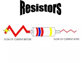
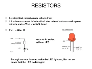
RESISTORS. Resistors limit current, create voltage drops All resistors are rated in both a fixed ohm value of resistance and a power rating in watts. (Watt = Volts X Amps) Unit -- Ohm Ώ. resistor in series with an LED.

E N D
RESISTORS • Resistors limit current, create voltage drops • All resistors are rated in both a fixed ohm value of resistance and a power rating in watts. (Watt = Volts X Amps) • Unit -- Ohm Ώ resistor in series with an LED Enough current flows to make the LED light up, But not so much that the LED is damaged
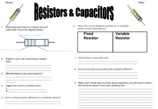
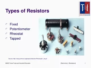
Fixed Resistor • 2. Variable Resistor TYPES Fixed Resistor Electric symbol Generic Variable Resistor Electrical Symbol
FIXED RESISTORS • Fixed-value resistors are divided into two category types of resistors: Carbon / Metal Oxide and Wire-Wound. Carbon and Metal Oxide flm Wire wound
CARBON RESISTORS • Carbon resistors are commonly used in electronic systems. • Carbon is mixed with binder; • the more carbon, the lower the resistance. • Carbon resistors have a fixed resistance value and are used to limit current flow. • They are rated in watts and most have color-code bands to show the resistance value. • A typical resistor has a watt rating from 0.125W to 2.0 W. Carbon Metal Oxide film
WIRE-WOUND RESISTORS • Made with coils of resistance wire. • Often enclosed in ceramic to help dissipate heat and protect the resistor wire, • Accurate and heat stable. • The resistance value is often marked. • Used in higher watt circuits often 2W or higher. • An ignition ballast resistor is an example of a wire wound resistor.
VARIABLE RESISTORS • Resistance increases with increasing length. It is possible to use this effect to build a variable resistor. • Resistance can be altered by changing the length of resistor in the circuit. The device below allows just that: Rotating the knob alters the length, and in turn the resistance. • Types • Rheostat • Potentiometer • Trimmer
RHEOSTAT • Rheostats have two connections, • one to the fixed end of a resistor and the other to a sliding contact on the resistor. • Turning the control moves the sliding contact away from or toward the fixed end, increasing or decreasing the resistance. • Rheostats control resistance, thus controlling current flow.
RHEOSTAT OPERATION • As the wiper moves along the rheostat it exposes more or less of the resistor. Moving the wiper towards the high places a small portion of the resistor in series with the light, causing the light to glow bright. Moving the wiper toward the low, places a larger portion of the resistor in series with the lamp; this increased resistance causes less current to flow lowering the intensity of the light. Rheostats are not used on computer circuits because of temperature variations on the resistor when the wiper arm is moved.
POTENTIOMETER • Used to measure changes in position. • Have three connections or legs: the reference, signal, and ground. • The reference is at one end of a resistor and the Ground is at the other end. • Current flows from the Reference through the resistor to Ground creating a voltage drop across the resistor. • The Signal is a sliding contact (movable wiper arm) that runs across the resistor. Unlike a rheostat, its main purpose is not to vary resistance but to vary the voltage in a circuit. Potentiometer SymbolVariable Resistor Symbol
POTENTIOMETER OPERATION • Remember a potentiometer has three legs, the reference (R), the signal (S) , and the ground (G) as shown below. 5 volts is supplied to the reference, current flows from the reference (R) through the entire resistor to ground (G). The Signal wiper slides across the resistor changing measure voltage as it moves. As the wiper moves towards the reference (R), the measured signal voltage at (S) will increase. As the wiper moves away from the Reference (R) towards ground (G), the measured signal voltage drops
POTENTIOMETER APPLICATIONS • Since potentiometer are used to measure changes in position they naturally are used for throttle, EGR, AC blend door, and power seat position sensors. All potentiometers have three wires and are used to measure position changes
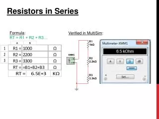
RESISTOR RATING COLOR BANDS • The first two bands set the digit or number value of the resistor. • The third band, also known as the multiplier band, is the number of zeros added to the number value. • The last band is the Tolerance band. Example: +/- 10%
RESISTOR COLOR BAND CHART • The chart below is used to interpret the color bands on the carbon resistor. Another chart is used to show the value of tolerance band colors
READING COLOR BANDS - RATING VALUE • The first color band is Green with a value of "5".The second color band is Red with a value of "2".The third band is Black with a value of "0" zero. (No zeros are added) • So the resistor has a base value of 52 ohms.
READING COLOR BANDS - TOLERANCE VALUE • Resistors vary in tolerance (accuracy). Common tolerance values are 20%, 10%, 5%, 2%, or 1%, simply meaning the maximum percent allowable difference the resistor value actually is from the designed value rating. A 1% resistor is a higher quality resistor than one with a 20% rating. • The tolerance band (last band) is silver with a value of 10%. So, the resistance value is "52 ohms plus or minus 5.2 ohms" (46.8 to 57.2 ohms).
CAPACITOR • A device used to store charge in an electrical circuit • functions much like a battery but charges and discharges much more efficiently • A basic capacitor is made up of two conductors separated by an insulator, or dielectric • The dielectric can be made of paper, plastic, mica, ceramic, glass, a vacuum or nearly any other nonconductive material Symbol of capacitor
CAPACITANCE • Measure of a capacitor's ability to store charge. • A large capacitance means that more charge can be stored • Measured in farads, symbol F. • However 1F is very large, • so prefixes are used to show the smaller values. • Three prefixes (multipliers) are used, µ (micro), n (nano) and p (pico): • µ means 10-6 (millionth), so 1000000µF = 1F • n means 10-9 (thousand-millionth), so 1000nF = 1µF • p means 10-12 (million-millionth), so 1000pF = 1nF
TYPES • Fixed capacitors • Electrolytic capacitors • Polarized capacitors • Nonpolarized capacitors • Ceramic capacitors • Plastic capacitors • Mica capacitors • Paper capacitors • Variable capacitors
FIXED CAPACITORS Electrolytic capacitors Polarized capacitor • have implicit polarity • can only be connected one way in a circuit • Symbol Nonpolarized capacitor • has no implicit polarity • can be connected either way in a circuit. • Eg Ceramic, mica
VARIABLE CAPACITORS • Mostly used in radio tuning circuits • Sometimes called “ tuning capacitors” • Have very small capacitance values • Ttypically between 100pF and 500pF (100pF = 0.0001µF) Variable Capacitor Symbol
DISSIPATION FACTOR • Measure of the power factor (or losses) of a capacitor • DF = 2 P fRC X 100%, where • R -- Equivalent Series Resistance (ESR) of the capacitor, • f -- frequency, • C -- capacitance. • Dissipation factor varies with frequency and temperature. • ESR -- measure of the total lossiness of a capacitor which includes the leads, electrodes, dielectric losses, leakage (IR) and most important, the end spray connecting the leads to the metallized film.
i Flux Current Inductors Inductor are used in electrical circuits because they store energy in their magnetic fields. What is an Inductor? A coil of wire that can carry current Current produces a magnetic field Energy is stored in the inductor
TYPES • Fixed inductors • Depending on the type of core used • Air core inductors • Iron core inductors • Ferrite core inductors • Variable inductors
FIXED INDUCTORS • Air core inductors • Consists of few turns of wire, wound on a hollow former • Generally used in radio frequency applications where very low value of inductance is required • Iron core inductors • Contains a number of turns of copper wire, wound on a hollow former • Generally used in low frequency applications such as filter circuits in power supplies or chokes in fluorescent tubes
FIXED INDUCTORS (contd…) • Ferrite core inductors • Made up of non-metallic compounds consisting mainly of ferric oxide in combination with one or two bivalent metal oxides • Appliocations • r.f. chokes for supply decoupling purpose • Switching regulated type dc power supplies • Various types of filters used in communication equipment
VARIABLE INDUCTORS • symbol • Hollow former has screw threads in the inner hollow portion • Similar matching threads are provided on the ferrite core which can be screwed in or out of the former • Because of the change of the position of the ferrite core, the value of the inductance changes • Maximum when ferrite core is fully in
Q of an Inductor • No power loss in an ideal inductor • But losses do occur in practicalinductor • 2 types of losses • Hysteresis and eddy current losses in the core • I2R loss Rs Ls Equivalent circuit of an Inductor Q = ω Ls / Rs
THE BIPOLAR JUNCTION TRANSISTOR • The bipolar junction transistor is a 3-terminal device consisting 2 layers of n-type material sandwiching a thin p-type layer or 2 layers of p-type material sandwiching a thin layer of n-type material. • These structures are appropriately called npn transistor and pnp transistor, respectively. • The terminals are called Emitter, Base and Collector. • The emitter is heavily doped, the base is lightly doped and collector is moderately doped.
• There are two types of BJTs, the npn and pnp • The two junctions are termed the base-emitter junction and the base-collector junction • The term bipolar refers to the use of both holes and electrons as charge carriers in the transistor structure • In order for the transistor to operate properly, the two junctions must have the correct dc bias voltages – the base-emitter (BE) junction is forward biased – the base-collector (BC) junction is reverse biased Forward-Reverse bias of a BJT
TRANSISTOR OPERATION For current to flow through the BJT its two p-n junctions (2 diodes back to back) must be properly biased. Typically, one junction is forward bias while the other is reverse bias. The figure below shows the biasing of a pnp transistor Notice that the emitter-base junction is forward biased while the collector-base junction is reverse biased. Majority carriers will flow from emitter to base across the forward biased junction. Because the base layer is very thin and has a high resistance (lightly doped) most of these carriers will diffuse across the reverse-biased junction into the collector in the same direction of the minority charges, and only tiny amounts of current will flow out of the base terminal. Typically collector currents are of the order of mA while base currents are μA. Appling Kirchhoff’s current law: IE = IC + IB
TRANSISTOR CURRENTS • Transistor Currents: IE = IC + IB • alpha (αDC) IC = αDCIE • beta (βDC) IC = βDCIB – βDC typically has a value between 50 and 500
TRANSISTOR VOLTAGES • DC voltages for the biased transistor: • Collector voltage VC = VCC - ICRC • Base voltage VB = VE + VBE – for silicon transistors, VBE = 0.7 V BJT operating modes
OPERATION MODE • Active: • Most importance mode, e.g. for amplifier operation. • The region where current curves are practically flat. • Saturation: • Barrier potential of the junctions cancel each other out causing a virtual short. • Ideal transistor behaves like a closed switch. • Cutoff: • Current reduced to zero • Ideal transistor behaves like an open switch.
BJT - operation in Active mode Active Mode Circuit Model
TRANSISTOR CONFIGURATIONS THE COMMON-BASE CONFIGURATION There are three types: Common-Base (CB), Common-Emitter (CE), and Common-Collector (CC). The base is common to both the input and the output, usually at ground potential. Features of CB Connection • Current Gain <1 • Power Gain>1 • Voltage Gain>1 • Low i/p Impedance • High o/p Impedance
THE COMMON-EMITTER CONFIGURATION • Emitter is common or reference to both input and output signal. • The CE configuration is the one most commonly encountered since it • provides both good current and voltage gain for ac signals. • In the CE configuration the input is between the base and the emitter. • The output is between the collector and the emitter.
THE COMMON-COLLECTOR CONFIGURATION OR EMITTER FOLLOWER • Collector is common to both input and output. Mainly used for current • amplification and impedance matching. • Characteristics curve is same as CE configuration • A typical transistor power amp will have a CE stage followed by a CC stage • Features of CC Connection • High Input Impedance • Low Output impedance • Voltage Gain < 1 • Power + Current Gain
SOME CHARACTERISTICS OF BJTS – A RECAP 1. An equivalent circuit of a NPN transistor is two diodes tied anode to anode; one cathode being the emitter, the other the collector, and the junction of the anodes is the base. 2. When a NPN transistor is in operation, there is always a constant 0.6 volt drop between the base and emitter, i.e., the base is always ~ 0.6 volts more positive than the emitter--always! 3. There is no output at the collector, until the base has reached ~ 0.6 volts and the base is drawing current, i.e., any signal that appears at the base that is not up to ~ 0.6 volts (and not drawing base current), is never seen at the collector. 4. The base requires a current, not a voltage to control the collector current. 5. The collector is a current source: it does not source a voltage. 6. The collector appears to output a voltage when a resistor is connected between it and power. 7. The collector is a high impedance when compared to the emitter.
SOME CHARACTERISTICS OF BJTS – A RECAP 8. The transistor can output an amplified signal either from the collector or the emitter (or both). 9. When operating with a collector resistor (RL): the output voltage from the collector is an amplified voltage. 10. When operating with only an emitter resistor (Re): the output voltage from the emitter is not an amplified voltage, because it is always ~ 0.6 volts, below the input (base) voltage--hence the name voltage follower. But because the emitter can source large amounts of current to the "LOAD," it can be said, there was CURRENT amplification. 11. The collector--being high impedance--cannot drive a low impedance load. 12. The emitter--being a low impedance--can drive a low impedance load. 13. The voltage gain from the collector is greater than one (Gv > 1). 14. The voltage gain from the emitter is less than one (Gv < 1). 15. Both the collector and the emitter: output ~ the same power: E x I = P.
Silicon Controlled Rectifier A Silicon Controlled Rectifier (or Semiconductor Controlled Rectifier) is a four layer solid state device that controls current flow The name “silicon controlled rectifier” is a trade name for the type of THYRISTOR commercialized at General Electric in 1957
Silicon Controlled Rectifier An SCR can be seen as a conventional rectifier controlled by a gate signal It is a 4-alternately doped semiconductor layers 3-terminal device. 3-leads are referred to as the Anode, Cathode, and Gate. When the gate to cathode voltage exceeds a certain threshold, the device turns 'on' and conducts current Which are used as electronically controlled switches
Silicon Controlled Rectifier The operation of a SCR can be understood in terms of a pair of tightly coupled Bipolar Junction Transistors used for the purpose of controlling electrical power while BJT's and FET's. Since they do not have the power handling capability SCR has three states: Reverse blocking mode, forward blocking mode, and forward conducting mode
V-I Characteristics of SCR • The V-I curve shows the relationship between VF and IF when the SCR's gate is open. • When a Forward voltage is applied to the SCR, • The SCR's cathode-to-anode voltage is designated as VF at this time. VF increases from zero, the SCR conducts only a small forward current (IF )which is due to leakage. As VF continues to increase, IF remains very low and almost constant but eventually a point is reached where IF increases rapidly and VFdrops to a low value. • The VF value required to trigger this sudden change is referred to as the Forward Breakover Voltage (Vp). When this value of Vp is reached the SCR simply breaks down, and conducts a high IF which is limited only by the external resistance in series with the device. • The SCR switches from the off state to the on state at this time. The drop in VF occurs because the SCR' s resistance drops to an extremely low value and most of the source voltage appears across the series resistor.
When the SCR is in the on state, only a slight increase in VF is required to produce a tremendous increase in IF. the SCR will remain in the on state as long as IF remains at a substantial value. Only when IF drops below a certain minimum value, will the SCR switch back to its off-state. This minimum value of IF which will hold the SCR in the on state is referred to as the SCR's Holding Current and is usually designated at IH . The IH value is located at the point where breakover occurs.