Modeling Partial Discharge Activity in Dielectric Insulation: Effect of Cavity Size and Location
This study presents a two-dimensional finite element analysis (FEA) model to investigate partial discharge (PD) activity in a spherical cavity within a dielectric insulation material. The model, consisting of a homogeneous dielectric with a cavity diameter and position varied, simulates the impact of these factors on PD behavior. By applying a 50Hz AC voltage, the study calculates physical and apparent charges, helping to predict crucial PD parameters. Insights from this model may assist in assessing the condition of electrical insulation systems by comparing experimental and simulation data.

Modeling Partial Discharge Activity in Dielectric Insulation: Effect of Cavity Size and Location
E N D
Presentation Transcript
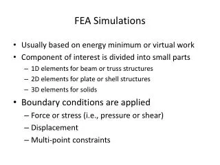
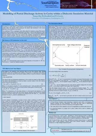
Modelling of Partial Discharge Activity in Cavity within a Dielectric Insulation MaterialTianyu Bai, D.J.Swaffield and P.L.LewinUniversity of Southampton, Southampton, UK The Simulation Model Introduction Fig.2 shows details of the two-dimensional (2D) model geometry that has been developed in FEA software . The model consists of a homogenous dielectric material of 1mm thickness and 10 mm diameter and a spherical cavity. The PD physical charge and apparent charge are calculated by time integration of current through the cavity center and through the ground electrode respectively. The horizontal line in the cavity center represents the area used to calculate the current for the PD physical charge calculation. A 50Hz sinusoidal voltage is applied at the upper electrode while the lower electrode is always grounded to study the effect of cavity size on PD activity, the cavity diameter is varied but its position is fixed in the middle of the material. To study the effect of cavity location within the dielectric material on PD activity, the cavity diameter is fixed but its location is varied between the upper and lower electrodes. This model has been reported in several publications [1,2] PD activity in a cavity within a solid dielectric material depends on the cavity size and its location within the material. This is because the electric field distribution in the cavity depends on the conditions of the cavity. The modelling of PD in a spherical cavity within dielectric material by using FEA method enables users to predict some PD parameters that relate to electric field distribution under different conditions of the cavity, such as PD repetition rate, maximum discharge amplitude and the inception voltage. This may assist in the condition assessment of electrical insulation systems through comparison of experimental data with simulation results The theory of PD behaviour in the void i PD frequency dependent behavior is mainly determined by three factors these are, the surface charge decay rate after a PD occurrence, the initial electron generation rate, which depends on the cavity surface time constant, and thirdly, the detrappable electron effective lifetime, . The effect of surface charge decay on PD frequency dependent activity is more significant if and are smaller than the period of the applied voltage. The temperature decay time constant, in the cavity also influences PD frequency dependent behavior if its value is comparable with the period of the applied voltage. A discharge in a void results in a deployment of charges on the surface of the void. The surface-charge density will attain such values that the field within the void will reduce until the discharge is quenched. In view of the principle of superposition, it is evident that the induced charge related to the charge distribution on can be expressed, in the form (1) In which is a dimensionless scalar function which depends on the position of only. The function is given by Laplace’s equation FEA Method and Test Object Fig.2. Complete 2D axial-symmetric model geometry This paper is an extension from previous work by the Tony Devices High Voltage Laboratory which has considered the modeling of PD activity in a spherical cavity within a dielectric material by using Finite Element Analysis (FEA) to study the influence of applied frequency. The cavity inception field is calculated by (4) Where , and are parameters of ionization processes characterization in the gas, is the pressure in the cavity and is the cavity radius . The corresponding cavity inception voltage and the applied inception voltage can be obtained through the FEA model. and are the voltage across the cavity and the applied voltage when the electric fieldin the cavity is equal to the inception field respectively. When the voltage across the cavity, , exceeds the inception voltage, , PD might occur with a condition that there is an initial free electron available. The total electron generation rate due to surface emission, , is written as • FEA EQUATIONS The electric field and temperature distributions in the model are solved by FEA software. The electric field distributions is solved by electric currents module of the FEA method, where the governing equation is (2) Where V is the electric potential, is the conductivity and is the permittivity. Whilst the temperature distribution in the cavity is solved using a heat transfer module by using (3) Where is temperature, is the mass density, is the specific heat capacity, is the thermal conductivity and is the heat source density. Equations (2) and (3) are coupled through the term, where is equal to the voltage across the cavity, and current through the cavity, ,which is calculated by (2). Where and are the electron generation rate due to surface emission and volume ionization (5) • TEST OBJECT Conclusions Current research is developing a sample of silicon rubber containing an artificial cavity. Fig.1 shows the schematic diagram of the test object which consists of an artificial spherical cavity of variable diameter placed in the middle of a dielectric material of 1 mm thick and 38 mm diameter. Silicon Rubber and hardener (mixture ratio of 10:1) has a small bubble injected into it during the cure process. The whole test object will be immersed in mineral oil to prevent surface discharges. A 50 Hz sinusoidal voltage will be applied to the test object. In order to study PD activity under different stresses and cavity conditions, different experiments will be undertaken. The experiments will investigate the effect of varying the applied voltage frequency and magnitude as well as investigate the effect of different spherical cavity diameters on PD behavior. • A Finite Element Analysis model describing a spherical cavity within a homogenous dielectric material has been developed. The model has been used to dynamically simulate PD activity as a function of frequency of the applied voltage. • The model will be further adopted to account for degradation processes within the void. • An experiment based on a single void in silicon rubber will be used to validate the modified model. References • [1] H.A.Illias,G.Chen, and P.L.Lewin “ Modelling of Partial Discharge Activity in Different Spherical Cavity Sizes and locations within a Dielectric Insulation Material,” International Conference on Properties and Applications of Dielectric Materials, pp. 485-488,2009. • [2] H.A.Illias,G.Chen, and P.L.Lewin “Modelling of surface charge decay in a spherical cavity within a solid dielectric material using Finite Element Analysis,” International Symposium on High Voltage Engineering,2009. tb6g10@ecs.soton.ac.uk University of Southampton, Highfield, Southampton, SO17 1BJ, UK Contact details : Figure 1. Schematic diagram of the test object