Download
1 / 7
70 likes | 159 Views
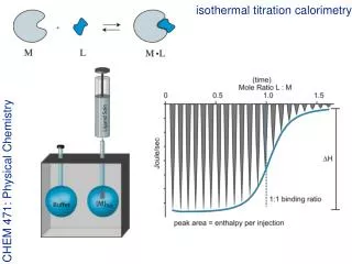
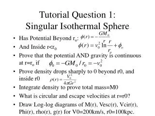
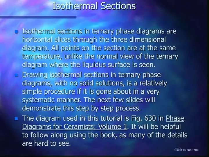
Isothermal Sections. Isothermal sections in ternary phase diagrams are horizontal slices through the three dimensional diagram. All points on the section are at the same temperature, unlike the normal view of the ternary diagram where the liquidus surface is seen.

E N D
Isothermal Sections • Isothermal sections in ternary phase diagrams are horizontal slices through the three dimensional diagram. All points on the section are at the same temperature, unlike the normal view of the ternary diagram where the liquidus surface is seen. • Drawing isothermal sections in ternary phase diagrams, with no solid solutions, is a relatively simple procedure if it is gone about in a very systematic manner. The next few slides will demonstrate this step by step process. • The diagram used in this tutorial is Fig. 630 in Phase Diagrams for Ceramists: Volume 1. It will be helpful to follow along using the book, as many of the details are hard to see. Click to continue
Tracing Isotherms • Trace the boundary of the diagram. • Identify and trace all the isotherms of the temperature for which you want the isothermal section, in this case 1400 oC. L • Identify the portion of the diagram where the liquidus surface is still below the temperature of interest and label this section: Liquid (L). L Click to continue
Intersection of Boundary Lines and Isotherms L L • At any point where the traced isotherm intersects a phase boundary line, including the edge of the diagram, draw a line from the intersection point back to the composition on either side of the phase boundary line. • From each composition that a line was drawn back to, draw tie lines to the liquidus line(s). Click to continue
Alkemades Lines L L • Draw in any alkemades lines that don’t come into contact with the liquidus line(s), or cross any of the tie lines drawn so far. Click to continue
Identifying Phase Regions • To understand the last step it is necceasary to describe the different regions of the isothermal section first. • There should now be up to four different regions on the isothermal section. • Liquid region, composed entirely of a liquid of varying composition. This region was labeled on the first slide. • Two Phase region, composed of a solid and a liquid. The composition of the liquid is found using the tie lines that were drawn in on the second slide. This region shares a border with the Liquid region. • Three Phase region, composed of two compositions and one unvarying liquid composition. This region is easily recognized by its sole point of contact with the Liquid region. • Solid region, composed of three solids. This region is triangular, and has no contact with the Liquid region. Click to continue
Labeling L L • Identify the phases present in each of the three different types of regions, and label each of the different regions in the diagram. • Two Phase Regions L8 • Three Phase Regions L1 • Solid Regions L7 L2 L3 Phases Present L6 L4 L5 CaO ·6Al2O3 + CaO ·Al2O3 ·2SiO2 + L6 2CaO ·SiO2 + 2CaO ·Al2O3 ·SiO2 + L4 2CaO ·Al2O3 ·SiO2 + CaO · Al2O3 + L11 2CaO ·Al2O3 ·SiO2 + CaO ·2Al2O3 + CaO ·6Al2O3 Al2O3 + CaO ·Al2O3 ·2SiO2 + 3Al2O3 ·2SiO2 3CaO · Al2O3 + 2CaO ·Al2O3 ·SiO2 + CaO ·2Al2O3 2CaO ·SiO2 + 2CaO ·Al2O3 ·SiO2 + L10 2CaO ·Al2O3 ·SiO2 + CaO ·6Al2O3 + L5 CaO ·6Al2O3 + CaO ·Al2O3 ·2SiO2 + Al2O3 CaO ·Al2O3 ·2SiO2 + 3Al2O3 · 2SiO2 + L7 3Al2O3 · 2SiO2 + SiO2 + L8 2CaO ·SiO2 + 3CaO · Al2O3 + L9 CaO ·SiO2 + 3CaO ·2SiO2 + L2 3CaO ·2SiO2 + 2CaO ·SiO2 + L3 3CaO ·SiO2 + CaO + 3CaO · Al2O3 2CaO ·SiO2 + 3CaO ·SiO2 + 3CaO · Al2O3 SiO2 + CaO ·SiO2 + L1 L10 2CaO ·Al2O3 ·SiO2 + Liquid CaO ·Al2O3 ·2SiO2 + Liquid 2CaO ·Al2O3 ·SiO2 + Liquid 12CaO ·7Al2O3 + Liquid 3Al2O3 ·2SiO2 + Liquid 3CaO ·2SiO2 + Liquid 3CaO ·Al2O3 + Liquid CaO ·6Al2O3 + Liquid 2CaO ·SiO2 + Liquid 2CaO ·SiO2 + Liquid CaO ·Al2O3 + Liquid CaO ·SiO2 + Liquid SiO2 + Liquid L11 L9 Click to continue
Things To Remember • Use the representative tie lines to determine the percent of each phase present in a Two Phase region, and to determine the liquid composition. • Use parallel lines in the Three Phase and the Solid regions to determine the percent of each phase present. • If making the isothermal section on a copy of a diagram, use colored pencils for the different steps. • Use tracing paper when the best results are desired. Click to Continue Main Menu