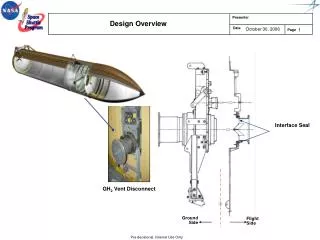
Design Overview and Constraints
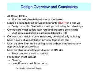
Design Overview and Constraints. 44 Barrel HEX’s 22 at the end of each Barrel (see picture below) Limited Space to fit all active components ( BOTH in r and Z) Design must also “live” within envelope defined by the cable trays. Connectors must satisfy leak rate and pressure constraints

Design Overview and Constraints
E N D
Presentation Transcript
Design Overview and Constraints • 44 Barrel HEX’s • 22 at the end of each Barrel (see picture below) • Limited Space to fit all active components (BOTH in r and Z) • Design must also “live” within envelope defined by the cable trays. • Connectors must satisfy leak rate and pressure constraints • Must pass qualification prescription defined by TRT • Connectors must, in some instances, be electrically isolating • Must have viable installation access (spanners etc) • Must be able filter the incoming liquid without introducing any appreciable pressure drop • Must be able to facilitate production at QM UoL • The production should be realistic • Production must include • Cleaning • Leak, Pressure and Flow checks. Paul Barclay p.j.barclay@rl.ac.uk
Realisation of the design solution ELECTRICAL ISOLATOR CERAMIC HEAT EXCHANGER Bheat1 Electrical isolation SCREEN Bcap1 Indium seal Bex1 Indium seal A Walk through the major components Paul Barclay p.j.barclay@rl.ac.uk
Side View of the Heat Exchanger SCT COOLING PRR 14-4-5HEAT EXCHANGER BODY 14mm I/D X-SEC 140mm FLATTENED PIPE 6.5 X 12.5 X 0.7W X-SEC 43mm TOTAL EXCHANGER LENGTH 1515 CURRENT Q.M.U.L. PROTOTYPE 1450 14 I/D X-SEC 140MM Paul Barclay p.j.barclay@rl.ac.uk
Realisation of the design solution as seen in Cryostat OPTICAL PATCH PANELS TRAY BARREL FITTINGS BARREL FITTINGS FLATTENED PIPE (PIPE-5) TD-1056-695 Another view of the major components Paul Barclay p.j.barclay@rl.ac.uk
Realisation of the design solution at A side 22 Heat Exchangers over 4 quadrants Blocks of 5 & 6 in cable trays VIEW LOOKING AT Z=0 A2-11 EXAMPLE A2-11 = END A QUADRANT 2 HEAT EX No 11 Paul Barclay p.j.barclay@rl.ac.uk
Realisation of the design solution at C side VIEW LOOKING AT Z=0 EXAMPLE END ………….C QUADRANT …3 HEAT EX No…12 C3-12 Paul Barclay p.j.barclay@rl.ac.uk
The Inlet Screen or Filter FLOW 264 Holes 0.5mm Dia 4.6 Dia Must inhibit flow of particles through to the capillary. R. Bates will address performance in his talk Paul Barclay p.j.barclay@rl.ac.uk
BHeat 1 Design Features SCT COOLING PRR 14-4-5Bheat1 Electrical Isolating Connector Details of the connectors (including qualification) will be given tomorrow FEMALE PEEK MALE PEEK SPRING NUT Paul Barclay p.j.barclay@rl.ac.uk
Status and Outlook • Design and Layout of the first of 11 variants is complete • All major design problems addressed and solved • Remaining 10 variants completed at the rate of 1 every 3 days • The differences between first and subsequent versions will be small • Design of the fabrication jig (with QM UoL) should take 3 weeks • All parts to make the HEX’s are ordered (for up to 60 Off) • Fabrication of some parts at RAL also started with parts delivered • Delivery has started • some parts started late (filters & SERTOs) Paul Barclay p.j.barclay@rl.ac.uk