Download
1 / 40
400 likes | 546 Views
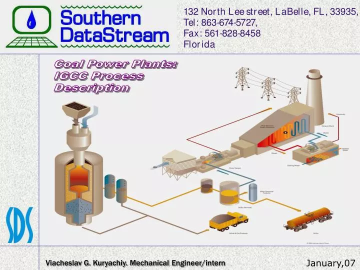
Coal Power Plants: IGCC Process Description. Viacheslav G. Kuryachiy. Mechanical Engineer/intern. January,07. Common structure of IGCC. 2. IGCC POWER PLANT UNITS. 1. Air separation Unit (ASU) 2. Gasification Unit 3. Gas Cooling unit 4. Gas Cleaning Unit 5. Sulfur Removing Unit

E N D
Coal Power Plants: IGCC Process Description Viacheslav G. Kuryachiy. MechanicalEngineer/intern January,07
IGCC POWER PLANT UNITS 1.Air separation Unit (ASU) 2. Gasification Unit 3. Gas Cooling unit 4. Gas Cleaning Unit 5. Sulfur Removing Unit 6. Gas Combustion Turbine Unit 7. Heat Recovery Steam Generator Unit 8. Steam Turbine Unit 3
Possible variants of Integrated Gasification Combine Cycle at Power Plants Source: 2003 Electric Power Research Institute, Inc. http://www.iea.org/dbtw-wpd/Textbase/work/2004/zets/technical/holt.pdf 4
1. Air separation Unit (ASU) The oxygen plant consists of a conventional, cryogenic air separation unit (ASU). The primary purpose of the ASU is to produce pressurized oxygen gas for the reaction with the coal slurry in the Gasifier and to produce nitrogen gas that is used as a diluent in the combustion turbine to control peak flame temperature thereby reducing the formation of NO, during syngas combustion. Secondary uses include low pressure oxygen for optimizing the Sulfur Recovery system and low pressure nitrogen for purging operations. Dulient Nitrogen to combuster Oxygen to gasifier Source:http://valleywatch.net/valleywatch/docs/Duke%20Edw.%20Application/Chapter2.pdf 5
Air separation Unit (ASU) The design for the air separation unit (ASU) is based on a high-pressure ASU with half of the air required by the ASU supplied from the combustion turbine. This level of integration was chosen to allow the ASU to operate independently of the gas turbine, but still obtain the efficiency advantage of an integrated system. Source: ECOS 2000, University of Twente Enschede, The Netherlands, July 5-7, 2000 http://www.airproducts.com/NR/rdonlyres/6753032F-A8B8-4339-A12F-BB1A8DB46735/0/ECOS.pdf 6
2. Gasification Unit O2 from ASU Coal Slurry Coal, water and oxygen are fed into a high-pressure gasifier, where the coal is partially combusted and converted into synthetic gas (“syngas”). The ash in the coal is converted to inert, glassy slag. Feed Water Radiant Syngas Cooler • 2.1. Classification of gasifiers. • Fixed bed gasifiers; • Fluidized bed gasifiers; • Entrained flow (slagging) gasifiers. High Pressure Steam Syngas Slag Source: The U.S. Department of Energy and Tampa Electric Company http://www.fossil.energy.gov/programs/powersystems/publications/Clean_Coal_Topical_Reports/topical19.pdf 7
Gasification Unit Moving-Bad Gasifier (Dry Ash) Source: Massachusetts Institute of Technology. Laboratory for Energy and the Environment. http://lfee.mit.edu/publications Publication No. LFEE 2005-002 WP http://lfee.mit.edu/public/LFEE_2005-002_WP5.pdf 8
Gasification Unit Fluidized-Bad Gasifier Source: Massachusetts Institute of Technology. Laboratory for Energy and the Environment. http://lfee.mit.edu/publications Publication No. LFEE 2005-002 WP http://lfee.mit.edu/public/LFEE_2005-002_WP5.pdf 9
Gasification Unit Entrained-Bed Gasifier Source: Massachusetts Institute of Technology. Laboratory for Energy and the Environment. http://lfee.mit.edu/publications Publication No. LFEE 2005-002 WP http://lfee.mit.edu/public/LFEE_2005-002_WP5.pdf 10
Gasification Unit At the outlet of the gasifier reactor the temperature of the syngas is around 1500 °C and the fly ash (or slag) is in liquid form. To protect downstream process equipment from fouling, a quench is needed to solidify the slag and make it non-sticky. There are four main alternatives for quenching: - Radiant syngas cooling - Water quench - Gas recycle quench - Chemical quench Source: Massachusetts Institute of Technology. Laboratory for Energy and the Environment. http://lfee.mit.edu/publications Publication No. LFEE 2005-002 WP http://lfee.mit.edu/public/LFEE_2005-002_WP5.pdf 11
Gasification Unit Unless the hot syngas has been totally quenched with water, it typically has a temperature of around 900 °C and therefore needs further cooling before downstream gas clean up processes. There are two classes of syngas coolers for steam production: - Fire tube boilers - Water tube boilers Both types have been operated successfully in different plants. Of the two types, fire tube boilers are lower in cost. In this design, the hot raw syngas flows inside the tubes, while high pressure steam is generated on the outside. This means that the tubes are subjected to an external pressure. Depending on the design, maximum steam pressure is between 100 and 150 bar. Water tube boilers can handle higher steam pressure. 12
Gasification Unit In the table below represented gasifiers from three biggest companies: Source: Massachusetts Institute of Technology. Laboratory for Energy and the Environment. http://lfee.mit.edu/publications Publication No. LFEE 2005-002 WP http://lfee.mit.edu/public/LFEE_2005-002_WP5.pdf 13
Gasification Unit TYPES OF COAL: • High Ranked Coal − Bituminous and Anthracite coal (“Eastern Coal”) − About 50% of the U.S. coal reserves Higher heating value Lower moisture content Lower mineral content Performs well in slagging gasifiers • Low Ranked Coal − Lignite and Sub-bituminous coal (“Western Coal”) − About 50% of the U.S. coal reserves − Does not perform well in slagging gasifiers Sasol fixed bed Transport gasifier (under development) Source: http://www.netl.doe.gov/technologies/coalpower/gasification/pubs/pdf/060516%20FSO%20Presentation.pdf 14
3. Gas Cooling Unit Gas cooling unit consists of low temperature gas cooling (LTGC), COS hydrolysis and Mercury removal. 3.1. LTGC In this section, the particulate-free syngas from the syngas scrubber is cooled and the heat is recovered by heating clean syngas and generating steam. Most of the water in the syngas is condensed and removed before it reaches the Acid Gas Removal (AGR) section. Source:http://valleywatch.net/valleywatch/docs/Duke%20Edw.%20Application/Chapter2.pdf 15
Gas Cooling Unit 3.2. COS Hydrolysis Each train of gas cooling contains a reactor for conversion of Carbonyl Sulfide (COS) to Hydrogen Sulfide (H2S) to enable more complete sulfur removal in the AGR. Source:http://valleywatch.net/valleywatch/docs/Duke%20Edw.%20Application/Chapter2.pdf 16
Gas Cooling Unit 3.3. Mercury removal Carbon beds remove 90-95% of the mercury from coal derived synthesis gas. Mercury sulfide on the spent carbon is stable and currently the best option is to dispose of it at certified storage sites. Regeneration with mercury recovery is complex and expensive. The carbon is impregnated with sulfur at a concentration of about 10-15 wt%. The mercury reacts with sulfur as the gas goes through the sulfur bed to form HgS. After the sulfur on the carbon is exhausted, the spent adsorbent is shipped to a hazardous chemicals disposal site. HgS is a very stable compound and its long-term storage presents no problems. The spent carbon can also be incinerated and the mercury recovered from the incinerator gas via cooling and condensation. Source:http://valleywatch.net/valleywatch/docs/Duke%20Edw.%20Application/Chapter2.pdf 17
Gas Cooling Unit Examples of syngas composition at scrubber outlet (mole %) Source: Massachusetts Institute of Technology. Laboratory for Energy and the Environment. http://lfee.mit.edu/publications Publication No. LFEE 2005-002 WP http://lfee.mit.edu/public/LFEE_2005-002_WP5.pdf 18
4. Gas Cleaning Unit The syngas is cleaned of particles. Next the syngas passes through a bed of activated charcoal, which captures the mercury. The sulfur is removed from the syngas and converted to either elemental sulfur or sulfuric acid for sale to chemical companies or fertilizer companies. • Particle removal • Metal Carbonyls • HCl Removal • “Shift Rx” option Source: Massachusetts Institute of Technology. Laboratory for Energy and the Environment. http://lfee.mit.edu/publications Publication No. LFEE 2005-002 WP http://lfee.mit.edu/public/LFEE_2005-002_WP5.pdf 19
Gas Cleaning Unit • Particle removal Dry solids removal systems use candle filters that can remove all solids from the gas at temperatures between 300 and 500 °C. Above 500 °C, alkali compounds may pass the filters in significant amounts. Below 300 °C, the filters may be blinded of deposits of ammonium chloride (NH4Cl). Including cyclones upstream will reduce the loading on the filters and therefore also the risk of breakage. Wet solids removal systems use water scrubbers operating at a temperature lower than the dew point of the gas so that the smallest solid particles can act as nuclei for condensation and ensure efficient operation. Even if an IGCC plant has a candle filter it usually also adds a wet scrubbing system for removal of remaining impurities such as chlorides and ammonia. 20
Gas Cleaning Unit • Metal Carbonyls Iron and nickel carbonyls (Fe(CO)5, Ni(CO)4) are both undesirable trace components in synthesis gases. Metal carbonyls are often present in synthesis gas that is made from petroleum residues. Nickel carbonyls are damaging to combustion turbines but can be removed from synthesis gas by activated carbon. Metal carbonyls can also be absorbed by low-temperature solvents such as used by the Rectisol process. These metal compounds, if not removed, wind up in the Claus plant feed, and are burned to FeS and NiS and then deposited on the Claus catalyst. Both of these outcomes are undesirable. 21
Gas Cleaning Unit • HCL removal Nahcolite (naturally occurring sodium bicarbonate), Trona (naturally occurring sodium sesquicarbonate), synthetic sodium carbonate/bicarbonate mixtures, Ca(OH)2, and other sorbents are effective for dry removal of HCl and HF from syngas. Sorbent requirements and performance depends on the gas conditions and the contaminant concentrations. Injection before the filter is necessary. 22
Gas Cleaning Unit • “Shift Rx” option Shift Rx – the additional process block for CO2 capture. It is a shift reactor in which the CO reacts with H2O to H2 and CO2. In the shift reactor, the heating value of the CO is transferred to H2 and the carbon atoms end up in the CO2 molecules. It has been found that a so called sour shift upstream the sulfur removal is more energy efficient and has lower cost than a clean shift downstream of the sulfur removal. CO+H2O⇔ H2+CO2 - 41.2 MJ/kmol (exothermic reaction) Source: Massachusetts Institute of Technology. Laboratory for Energy and the Environment. http://lfee.mit.edu/publications Publication No. LFEE 2005-002 WP http://lfee.mit.edu/public/LFEE_2005-002_WP5.pdf 23
Gas Cleaning Unit • “Shift Rx” option: IGCC with CO2 capture Source: Massachusetts Institute of Technology. Laboratory for Energy and the Environment. http://lfee.mit.edu/publications Publication No. LFEE 2005-002 WP http://lfee.mit.edu/public/LFEE_2005-002_WP5.pdf 24
5. Sulfur Removal Unit The sulfur is removed from the syngas and converted to either elemental sulfur or sulfuric acid for sale to chemical companies or fertilizer companies. Sulfur removal Acid gas removal (AGR) Sulfur recovery unit (SRU) Tail gas treating (TGT) Source: Massachusetts Institute of Technology. Laboratory for Energy and the Environment. http://lfee.mit.edu/publications Publication No. LFEE 2005-002 WP http://lfee.mit.edu/public/LFEE_2005-002_WP5.pdf 25
Sulfur Removal Unit Acid Gas Removal (AGR) Currently, the processes of choice in commercial IGCC facilities for the removal of acid gases are both the chemical solvent AGR processes based on aqueous methyldiethanolamine (MDEA) and the physical solvent-based Selexol process—which uses mixtures of dimethyl ethers of polyethylene glycol. In most of the IGCC applications now, with both of these AGR processes, the AGR units are preceded by carbonyl sulfide (COS) hydrolysis units to convert most of the COS to H2S. This then enables the AGR units to accomplish deeper total sulfur removal and lower H2S levels. Total sulfur (COS+H2S) levels of <20 ppmv may be required if selective catalytic reduction (SCR) is to be used with IGCC—to prevent ammonium sulfate salt deposition and corrosion problems in the colder sections of the heat recovery steam generator (HRSG). Source: Massachusetts Institute of Technology. Laboratory for Energy and the Environment. http://lfee.mit.edu/publications Publication No. LFEE 2005-002 WP http://lfee.mit.edu/public/LFEE_2005-002_WP5.pdf 26
Gas Cleaning Unit • Sulfur removal • The AGR process removes the sulfur from the syngas. In current GCC plants, the two processes of choice are based on absorption in a liquid solvent: - Chemical solvents based on aqueous methyldiethanolamine (MDEA); - The Selexol process based on a physical solvent; - Rectisol; - Mixed chemical/physical. The first both methods are capable of reducing total sulfur (H2S + COS) to levels below 20 ppmv in the cleaned syngas. For CO2 capture a second stage AGR would be added to remove the CO2 from the sulfur free syngas. If the syngas will be used to produce chemicals, deep sulfur removal will be required to protect the catalyst downstream. In this case the more expensive Rectisol physical solvent AGR process may be applied. This process is a standard solution in chemical applications such as methanol and ammonia. Chemical solvents AGR processes also require steam in the stripping process to regenerate the solvent, while physical solvents are regenerated only by staged flashing techniques. Source: http://www.netl.doe.gov/technologies/coalpower/gasification/pubs/pdf/ SFA%20Pacific_Process%20Screening%20Analysis_Dec%202002.pdf 27
Gas Cleaning Unit • Sulfur removal • The AGR process. In CO2 removal applications, the Selexol process is chilled — thus facilitating deep H2S removal as well as CO2 removal. The Rectisol physical solvent AGR process — based on low-temperature (refrigerated) methanol — is capable of deep total sulfur removal, but it is regarded as the most expensive AGR process. Therefore, its use is generally reserved for chemical synthesis gas applications in which very pure syngas is required. Its use in IGCCs with CO2 removal has also been proposed. Source: Massachusetts Institute of Technology. Laboratory for Energy and the Environment. http://lfee.mit.edu/publications Publication No. LFEE 2005-002 WP http://lfee.mit.edu/public/LFEE_2005-002_WP5.pdf 28
Gas Cleaning Unit • Sulfur removal - Methyldiethanolamine (MDEA): MDEA is the amine scrubbing process. Itdoes not combine with COS chemically. Only limited physical COS absorption takes place with MDEA. COS can be physically removed by MDEA only with very high solvent circulation rates, at which point the CO2 is also removed quantitatively. For synthesis gases that contain appreciable quantities of COS, prior removal of the COS is usually required. A catalytic hydrolysis unit is usually employed ahead of the MDEA unit as was done at the Tampa Electric gasification plants. Source: Massachusetts Institute of Technology. Laboratory for Energy and the Environment. http://lfee.mit.edu/publications Publication No. LFEE 2005-002 WP http://lfee.mit.edu/public/LFEE_2005-002_WP5.pdf 29
Gas Cleaning Unit • Sulfur removal - Selexol process: The Selexol process solvent is a mixture of dimethyl ethers of polyethylene glycol, and has the formulation CH3O(CH2CH2O)nCH3 where n is between 3 and 9. The Selexol process uses a physical solvent to remove acid gas from streams of synthetic or natural gas. The process may be regenerated either thermally, by flashing, or by stripping gas. The Selexol process is ideally suited for the selective removal of H2S and other sulfur compounds, or for the bulk removal of CO2. Source: Massachusetts Institute of Technology. Laboratory for Energy and the Environment. http://lfee.mit.edu/publications Publication No. LFEE 2005-002 WP http://lfee.mit.edu/public/LFEE_2005-002_WP5.pdf 30
Gas Cleaning Unit • Sulfur removal - Selexol process: Acid gas partial pressure is the key driving force for the Selexol process. Typical feed conditions range between 300 and 2000 psia with acid gas composition (CO2 + H2S) from 5% to more than 60% by volume. The product specifications achievable depend on the application and can be anywhere from ppmv up to percent levels of acid gas. Source: Massachusetts Institute of Technology. Laboratory for Energy and the Environment. http://lfee.mit.edu/publications Publication No. LFEE 2005-002 WP http://lfee.mit.edu/public/LFEE_2005-002_WP5.pdf 31
Gas Cleaning Unit • Sulfur removal - Selexol process: Acid gas partial pressure is the key driving force for the Selexol process. Typical feed conditions range between 300 and 2000 psia with acid gas composition (CO2 + H2S) from 5% to more than 60% by volume. The product specifications achievable depend on the application and can be anywhere from ppmv up to percent levels of acid gas. Source: Massachusetts Institute of Technology. Laboratory for Energy and the Environment. http://lfee.mit.edu/publications Publication No. LFEE 2005-002 WP http://lfee.mit.edu/public/LFEE_2005-002_WP5.pdf 32
Gas Cleaning Unit • Sulfur removal - Recticol process: The Rectisol process uses chilled methanol at a temperature of about -40°F to -80°F. Methanol’s selectivity for H2S over CO2 at these temperatures is about 6/1, a little lower than that of Selexol at its usual operating temperature. However, the solubilities of H2S and COS in methanol, at typical process operating temperatures, are higher than in Selexol and allow for very deep sulfur removal (<0.1 ppmv H2S plus COS). Rectisol’s high selectivity for H2S over CO2, combined with the ability to remove COS, is the primary advantage of the process. Chilled methanol also absorbs HCN, NH3, and iron- and nickel-carbonyls. The solubilities of these trace components and other organic sulfur compounds are even higher than that of H2S. Rectisol’s complex scheme and the need to refrigerate the solvent are its main disadvantages, resulting in high capital and operating costs. Source: Massachusetts Institute of Technology. Laboratory for Energy and the Environment. http://lfee.mit.edu/publications Publication No. LFEE 2005-002 WP http://lfee.mit.edu/public/LFEE_2005-002_WP5.pdf 33
Gas Cleaning Unit • Sulfur removal - Mixed chemical/physical: The mixed chemical/physical processes usually employ mixtures of an amine and a physical solvent in an effort to capture the best characteristics of each solvent. The best known example of the mixed/chemical solvent process is Sulfinol, a mixture of sulfolane (tetrahydrothiophene dioxide) and an aqueous solution of an amine, either DIPA (diisopropanol amine) or MDEA. 34
Gas Cleaning Unit • Sulfur recovery unit (SRU) • The standard solution for the SRU is the Claus process which produces elemental sulfur from H2S by substoichiometric combustion with air or oxygen. Many versions of this process are available. The sulfur may be fixed as elemental sulfur in liquid or solid form, or as sulfuric acid. The thermodynamics of the Claus process is such that one does not achieve high enough degrees of sulfur recovery without some treating of the tail gas, which usually contain mostly H2S and SO2, but also small amounts of COS, CS2 and elemental sulfur vapors. 35
Gas Cleaning Unit • Tail gas treating (TGT) The principal current tail gas treating approach is to hydrogenate/hydrolyze the sulfur species in the tail gas and then scrub out the resulting H2S in an acid gas removal absorber. This approach is capable of boosting total sulfur recovery to well over 99.9%. In some IGCC plant designs Claus tail gas, after H2S scrubbing, is compressed and routed to the combustion turbine. This tail gas handling eliminates the need for a tail gas incinerator and provides additional fuel and mass flow to the combustion turbine. H2S can be scrubbed in a stand alone separate process, or could be routed to the acid gas removal unit upstream of the Claus plant. Tail gas treating of this type will remain the dominant and a required step in order to meet the proposed regulations. 36
Gas Cleaning Unit • Tail gas treating (TGT) TGT alternatives: a) Dedicated absorber for H2S in TGT. b) Integration with upstream absorber for H2S capture Source: Massachusetts Institute of Technology. Laboratory for Energy and the Environment. http://lfee.mit.edu/publications Publication No. LFEE 2005-002 WP http://lfee.mit.edu/public/LFEE_2005-002_WP5.pdf 37
6. Gas Combustion Turbine Unit The gas turbine is integrated with the Air Separation Unit. From the compressor exhaust, a bleed stream is used to supply 50% of the air supply needed for the ASU. An additional bleed, 14% of the compressor discharge air, is chilled to 600 F and used for cooling in the turbine expander. Heat recovered from the air cooler is used in the steam cycle. The compressor discharge supplies air for use in the HGCU regenerator. The remainder of the compressor discharge air is used to combust the clean fuel gas. The ASU returns a nitrogen stream to the gas turbine combustor to assist in NOX control and to increase the flow rate and the power generated in the turbine expander. Combustor duct cooling is accomplished using intermediate pressure steam supplied from the steam bottoming cycle. This reheated steam is returned to the steam cycle. The combustor exhaust gases enter the expander where energy is recovered to produce power. 38
7. Heat Recovery Steam Generator The gas turbine exhausts into a HRSG (Heat Recovery Steam Generator), which generates high temperature superheated steam. This steam is injected into the gas turbine and expanded through it to increase the electrical power output. Variations in process steam requirements are handled by varying the fuel input to the duct burner located between the superheater and the evaporator. A simple cogeneration system typically consists of a HRSG located behind a gas turbine. This system is efficient when the thermal load is held nearly constant. When the thermal load drops below the design point the operating economics of the system are penalized. Cheng Cycle System Source: The American Society of Mechanical Engineers. Industrial Power Conference - PWRVol. 4 Editor: B. L. http://www.ecoxy.com/download/heat_recovery_steam_generator_for_cheng.pdf 39
8. Steam Turbine Unit The steam turbine converts heat energy into mechanical motion. Steam turbine is an action turbine (no reaction turbine), i.e. the steam jet meets from a being certain nozzle the freely turning impeller. There's a high pressure in front of the turbine, while behind it a low pressure is maintained, so there's a pressure gradient: Steam shoots through the turbine to the rear end. It delivers kinetic energy to the impeller and cools down thereby. Steam is produced in Gas Combustion Turbine. Then it heated in HRSG unit and goes to the steam turbine. The mechanical energy from the turbine through the generator converts to electrical energy. Steam doesn't escape then, it is condensed in a condensor and then pushed back into the cycle. 40