Download
1 / 19
220 likes | 571 Views
III-V HETEROJUNCTION BIPOLAR TRANSISTORS. Yan Yan Department of Electrical Engineering University of Notre Dame, Notre Dame, IN 46556-5637 April 27, 2004. III-IV BIPOLAR TRANSISTOR TECHNOLOGY. Characteristic Parameters Current gain Cutoff frequency / Speed Parasitic capacitances

E N D
III-V HETEROJUNCTION BIPOLAR TRANSISTORS Yan Yan Department of Electrical Engineering University of Notre Dame, Notre Dame, IN 46556-5637 April 27, 2004
III-IV BIPOLAR TRANSISTOR TECHNOLOGY Characteristic Parameters • Current gain • Cutoff frequency / Speed • Parasitic capacitances Methods to improve performances • Device design • Choice of material systems
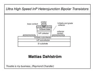
GaInAs/InP Buried Metal HBT- REDUCTION OF BASE-COLLECTOR CAPACITANCE • Buried Tungsten wires of the same area as the emitter metal was used to reduce CBCext • SBCT of BM-HBT was estimated to be 22% that of conventional HBT, CBC 30% of conventional HBT • fT = 86 GHz, fMAX > 135 GHz of device with an emitter area of 0.5 x 2.5 μm2 • fT = 82 GHz, fMAX > 200 GHz of device with an emitter area of 0.3 x 1.5 μm2 Schematic view of fabricated BM-HBT
I – V Characteristics • Current gain about 70 at the • collector voltage of 4V • S-parameters were measured • from 50 MHz to 30 GHz using • an HP8722 network analyzer • Extrapolations of fT and fMAX were • carried out from the -20dB/decade • regions of current gain (|h21|2) • and Mason’s unilateral gain (U), • respectively • the values of fT and fMAX reached • peak points (fT = 33.5 GHz, fMAX = • 47.3 GHz) at IC = 4mA and VC = • 6V Common-emitter collector I-V characteristics of BM-HBT with an emitter area of 2x10 μm2
SEM image of BM-HBT SEM image of the fabricated BM-HBT with an Emitter width of 0.3 μm after formation of the Dummy mesa. Good alignment between the Wires and the emitter is observed. A SEM view of a cross section cut by a focuse Ion beam. Measured collector thickness was 290 nm.
AlGaAs-GaInP Composite Emitter in GaInP/GaAs HBT- Improved Emitter Transit Time Emitter Transit Time
Composite Graded Emitter vs. Conventional Emitter • Self-aligned HBTs are grown by CBE • (chemical beam epitaxy) • Increase in fT from 44 GHz to 62 GHz • CBE 3 times lower for composite emitter • HBT without significant IC variation • Common limitation in high speed • performance of HBTs: large CBE (limited • mobile carrier transport thus charges • accumulation in the emitter) • Composite graded AlGaAs layer forms • an electron launcher at the interface • with the GaInP layer, which injects the • electrons at a higher kinetic energy • toward the remaining part of the emitter, • It leads to lower free carrier • concentration (Qe) and smaller CBE Energy band diagram of GaInP/GaAs (a)Composite emitter (b)conventional design HBT
Comparison of eletric field and electron density • Compositonally graded AlGaAs emitter • HBTs have much stronger electric • fields present in the emitter • The electron density is dramatically • decreased due to the presence of a • drift velocity component in this region • of the emitter • GaInP conventional emitter HBTs do • not have a built-in electric field within • the emitter region, and the electron • density in this case is increased due • to slow transport of carriers and thus • carrier accumulation Comparison of (a)electric field and (b)electron density Profiles for GaInP conventional and AlGaAs0GaInP composite emitter design HBTs.
Comparison of electron velocity • The figure focuses on the velocity • characteristics responsible for the • improved frequency characteristics • In the case of the composite emitter • design, the electron velocity is high • due to the drift velocity component • in the special emitter region • On the other hand, the electron • velocity of the conventional emitter • design is slower since diffusion • carrier transport is dominant in the • emitter region, which consists only • of GaInP • An estimate of זE using simulation • to evaluate ∆Qe/∆Jc showed values • of 0.13ps and 0.57ps, respectively. Comparison of electron velocity profiles for GaInP conventional and AlGaAs-GaInP emitter design HBTs in the composite emitter region
Comparison of CBE and fT • CBE for a composite emitter HBT • was found to be at least 3 times • lower than the conventional emitter • HBT under high IC operation • CBE for a composite emitter HBT • presents a weak Jc dependence • fT was improved from 44 GHz to • 62 GHz by using the composite • emitter in the HBT Comparison of CBE and fT characteristics for GaInP/ GaAs HBT (a)composite emitter and (b)conventional emitter
InGaP/GaAs HBT with WSi/Ti Electrode and Buried SiO2 in the Extrinsic Collector- decrease of emitter size and CBC • The width of the base contact is reduced • by using a self-aligning process • The buried SiO2 reduces the parasitic • capacitance because the dielectric constant • of SiO2 is about 1/3 of that of GaAs • WSi/Ti is used as the base electrode instead • of conventional gold-based electrode. Both • WSi and Ti can be deposited by sputtering • with good step coverage and selectively • patternede on GaAs and SiO2 by RIE. A thin • Ti film inserted between WSi and GaAs • reduces the contact resistance, and made it • possible to reduce the width of the base • contact without the large increase in the • base resistance • The emitter size effect on current gain was • suppressed by using InGaP as the emitter Schematic cross-section of device structure: (a)Conventional HBT and (b)small-scale HBT with a WSi/Ti base electrode and buried SiO2
Device Performance • The DC current gain of 20 is obtained for an HBT with SE of 0.3 x 1.6 μm2 due to the suppression of emitter size effect by using InGaP as the emitter material; • An HBT with SE of 0.6 x 4.6 μm2 exhibited fT of 138 GHz and fmax of 275 GHz at IC of 4 mA; • An HBT with SE of 0.3 x 1.6 μm2 exhibited fT of 96 GHz and fmax of 197 GHz at IC of 1 mA
Motivation for work in InAs bipolar transistors Historic trend – Increased the amount of Indium in the base of a HBT • Higher electron mobility & saturation velocity → shorter base transit time • Improved base resistance/base contact resistance • Faster device Advantages compared to the traditional III-Vs • Lower electron effective mass (0.022 m0) • Higher electron mobility (up to 33000 cm2 V-1 sec-1 at room temperature) • Higher peak velocity
Cracking study of AlxIn1-xAs on InAs AlxIn1-xAs grown on an InAs substrate is tensile stained, and there exists a critical thickness for the epilayer to form cracks to relieve strain • Two spicific regions of interest • were studied, one with low Al • concentration (7-9%) for the • HBT devices, and one with • higher Al concentration (40- • 50%) for other devices. • For x=9%, maximum thickness • is around 450 Å • Samples were examined by • Normarski contrast interference • Microscopy to determine whether • they were cracked or crack free AlxIn1-xAs epilayers on InAs substrates as a function of Al composition
InAs HBT device structure and I-V Room temperature common emitter J-V characteristics of an InAs HBT Device structure of InAs BJT and HBT devices βmax for BJT is 50, βmax for HBT is 100
SUMMARY • Base collector capacitance reduced by as high as 70% in BM-HBT • Base emitter capacitance reduced to one-third by composite InGaP/GaAs emitter • Parasitic capacitance reduced by 50% in InGaP/GaAs HBT using WSi base electrode and buried SiO2 layer • First results for InAs bipolar transistors (β ~ 100)
Reference • T. Arai, Y. Harada, S. Yamagami, Y. Miyamoto, K. Furuya, “First fabrication of GaInAs/InP buried metal heterojunction bipolar transistor and reduction of base-collector capacitance”, Jpn. J. Appl. Phys., Vol. 39 (2000), pp. L503-505 • T. Arai, S. Yamagami, Y. Miyamoto, K. Furuya, “Reduction of base-collector capacitance in submicron InP/GaInAs heterojunction bipolar transistors with buried tungsten wires”, Jpn. J. Appl. Phys., Vol. 40 (2001), pp. L735-L737 • T. Arai, S. Yamagami, Y. Miyamoto, and K. Furuya,“Fabrication of submicron buried metal heterojunction bipolar transistor by EB-lithography”, www.pe.titech.ac.jp/qee_root/symposium/ PDF/araimiyamoto.pdf • J. Park, D. Pavlidis, S. Mohammadi, J. Guyaux and J. Garcia, “Improved emitter transit times using AlGaAs-GaInP composite emitter in GaInP/GaAs heterojunction bipolar transistors”, IEEE transactions on Electron Device. Vol. 48, No. 7, July 2001, pp1297-1303 • T. Oka, K. Hirata, H. Suzuki, K. Ouchi, H. Uchiyama, T. Tanguchi, K. Mochizuki and T. Nakamura, “High speed small-scale InGaP/GaAs HBT technology and its application to integrated circuits”, IEEE transactions on electron devices, vol. 48, No. 11, Nov 2001, pp.2625-2630
Reference • T. Oka, K. Hirata, K. Ouchi, H. Uchiyama, K. Mochizuki and T. Nakamura, “ Small-scale InGaP/GaAs HBT’s with WSi/Ti base electrode and buried SiO2”, IEEE transactions on electron devices, vol. 45, No. 11, Nov 1998, pp.2276-2282 7. K. Averett, S. Maimon, X. Wu, M. Koch and G. Wicks, “InAs-based bipolar transistors grown by molecular beam epitaxy”, Journal of vacuum science technology B, 20 (3), May/Jun 2002, PP. 1213-1216 8. S. Maimon, K. Averett, X. Wu, M. Koch, and G. Wicks, “InAs-based heterojunction bipolar transistors”, Electronics letters, vol. 38, No. 7, pp. 344-346 9. P. Dodd, M. Melloch, M. Lundstrom, J. Woodall, and D. Petit, “InAs bipolar transistors: a path to high performance cryogenic electronics”, IEEE transactions on electron devices, Vol. 40, No. 11, Nov 1993, pp. 2141