Download
1 / 22
240 likes | 555 Views
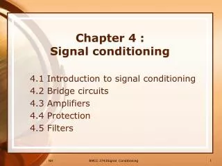
Princess Sumaya Univ. Electronic Engineering Dept. 3441 Industrial Instruments 1 Chapter 3 Digital Signal Conditioning. Dr. Bassam Kahhaleh. Digital Signal Conditioning. Objective Introduce the basic technique of digital signal conditioning, especially interfacing, in process control.

E N D
Princess Sumaya Univ.Electronic Engineering Dept. 3441Industrial Instruments 1Chapter 3Digital Signal Conditioning Dr. Bassam Kahhaleh
3441 - Industrial Instruments 1 Digital Signal Conditioning Objective Introduce the basic technique of digital signal conditioning, especially interfacing, in process control.
3441 - Industrial Instruments 1 Digital Signal Conditioning Digital Signals Pressure Level Temperature
3441 - Industrial Instruments 1 Digital Signal Conditioning Digital Signals TTL Output • Totem-pole • Tri-state • Open-collector I H = 0.04 mA I H = 0.4 mA I L = 1.6 mA I L = 16 mA
3441 - Industrial Instruments 1 Digital Signal Conditioning TTL Interfacing • Never leave inputs unconnected • Never short-circuit outputs to ground or Vcc • Never short-circuit outputs together unless they are tri-state or open-collector outputs • Never use pull-down resistors • Be careful when using different power supplies (VCC1 = +5, VCC2 = +12).
3441 - Industrial Instruments 1 Digital Signal Conditioning TTL Interfacing What is the minimum resistance value? When the tri-state output is floating: V should be max 0.8, IR = 1.6 mA R = 0.8 / 1.6 = 0.5 KΩ V IR Now what happens when the tri-state output goes high? V should be min 2.4 V, therefore IR = 2.4 / 0.5 K = 4.8 mA !!
3441 - Industrial Instruments 1 Digital Signal Conditioning TTL Interfacing +VCC +VCC Typically, R = 10 KΩ IR max = (5 – 0.2) / 10 = 0.48 mA IR V Now what is the value of V when the tri-state outputs goes floating? IR = 0.04 mA V = 5 – 0.04 x 10 = 4.6 Volts
3441 - Industrial Instruments 1 Digital Signal Conditioning TTL Interfacing +VCC LED: V = 1.5 ~ 1.6 V I = 10 ~ 15 mA IR R Vo Standard TTL gates should not source such current to a LED, but it can sink it. What is the minimum value of R? VO max = 0.8 V, IR = 15 mA R = (5 – 1.5 – 0.8) / 15 = 0.18 KΩ Typically, VO max = 0.2 V, IR = 15 mA, R = 220 Ω
3441 - Industrial Instruments 1 Digital Signal Conditioning TTL Interfacing +VCC2 +VCC1 VCC2 > VCC1 IR R Vo
3441 - Industrial Instruments 1 Digital Signal Conditioning TTL Interfacing Relay current = 40 mA β = 100 IB = 0.4 mA R = (2.4 – 0.7) / 0.4 = 4.25 KΩ R
+ − + − 3441 - Industrial Instruments 1 Digital Signal Conditioning Converters Comparators 2.2 mV/°C T 0.352 V Alarm 0.2 V / kPa P 2.0 V Comparators’ Power Supply?
+ − 3441 - Industrial Instruments 1 Digital Signal Conditioning Converters Hysteresis Comparators Vout R f VO R Vin Vout Vref 0 Vin VL VH
3441 - Industrial Instruments 1 Digital Signal Conditioning Converters Digital-to-Analog Converters (DAC) Bipolar DAC Conversion Resolution?
− + 3441 - Industrial Instruments 1 Digital Signal Conditioning R Converters R-2R ladder DAC R R R V out 2R 2R 2R 2R 2R b0 b1 b2 b3 VR
RTH = R − + VTH = ½ VR 3441 - Industrial Instruments 1 Digital Signal Conditioning R Converters R-2R ladder DAC R R R V out 2R 2R 2R 2R 2R VR
RTH = R − + VTH = ¼ VR 3441 - Industrial Instruments 1 Digital Signal Conditioning R Converters R-2R ladder DAC R R R R V out ½ VR 2R 2R 2R
3441 - Industrial Instruments 1 Digital Signal Conditioning Converters Analog-to-Digital Converters (ADC) Bipolar ADC Conversion Resolution?
3441 - Industrial Instruments 1 Digital Signal Conditioning Converters Parallel Feedback ADC SC VX Logic CountingNetwork EOC bn-1 bn-2 b1 b0 Comparator ... DAC
C bn-1 bn-2 b1 b0 Digital Counter R −VX − + +VR Comparator Logic Control EOC SC 3441 - Industrial Instruments 1 Digital Signal Conditioning Converters Ramp ADC (Dual-Slope) VO V1 t 0 T1 t x VO
3441 - Industrial Instruments 1 Digital Signal Conditioning Converters Conversion-Time Consequences Vi VN+1 VN t C
+ − 3441 - Industrial Instruments 1 Digital Signal Conditioning Converters Sample-and-Hold (S/H) Vc(t) Vin(t) ADC C S/H
3441 - Industrial Instruments 1 Digital Signal Conditioning End of Chapter 3