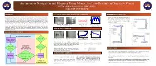
CNC Turning
CNC Turning. Module 1: Introduction to CNC Turning. Watch the following video, and answer the following questions:. Module Objectives. 1. Define the term CNC. 2. Recognize the advantages and disadvantages of CNC.


CNC Turning
E N D
Presentation Transcript
CNC Turning Module 1: Introduction to CNC Turning
Watch the following video, and answer the following questions:
Module Objectives 1. Define the term CNC. 2. Recognize the advantages and disadvantages of CNC. 3. Differentiate between Cartesian and Polar coordinate systems used in CNC programming. 4. Recognize the turning machine axes. 5. Identify the positive and negative movement directions on the turning CNC machines. 6. Describe the difference between absolute and incremental dimensioning methods.
Introduction CNC stands for Computer Numerical Control. It is the technology of controlling a machining operation using a computer program, which is called Numerical Control (NC) Program. In other words, a computer rather than a person will directly control the machine tool.
Introduction The most important computerized machine tools that are used extensively in the industry are: CNC Turning (Lathe) machine CNC Milling machine
Advantages of CNC • Increased speed at which parts are produced (productivity). • Producing the same quality for all work parts. • Better dimensional accuracy which gives exact and correct dimensions. • Increased ability to produce difficult parts. • Less scrap.
Disadvantages of CNC • High initial cost • Need high qualified operator.
Coordinate Systems In order to shape metal by machine tools, the cutting tool should move in contact with the workpiece at certain specific points, while the workpiece or cutting tool is rotating. Coordinate system is required to define the movement on the machine.
Coordinate Systems Basically there are two common coordinate systems: Polar coordinate system Cartesian coordinate system
Example 1 Locate points P1 through P4 on the coordinate system shown in Fig. 1.4 P1 X = 80 Y = 60 P2 X = -80 Y = 20 P3 X = -50 Y = -60 P4 X = 60 Y = -70
Example 2 How can you describe the line given in the figure using polar coordinate system?
CNC Lathe (turning) Machine’scoordinate system: To ensure that the control system of the machine will read the specified coordinates correctly to indicate the position of the workpiece; the machine tool has its own "coordinate system“.
CNC Lathe (turning) Machine’scoordinate system: The following points are part of this system. • Machine Zero point (M) • Workpiece Zero Point (W)
CNC Lathe (turning) Machine’scoordinate system: The following points are part of this system. Workpiece Zero point Machine Zero point
Turning Machine axes CNC Turning machine has at least 2 controllable feed axes, marked as X and Z; Fig. 1.8
Turning Machine axes When the cutting tool moves toward and backward the machine spindle, this is called movement along Z axis. When the cutting tool moves in cross direction to the longitudinal axis of the workpiece, this is called movement along X axis.
Turning Machine axes Positive Z direction is when the tool moves away from the workpiece in Z axis. Positive X direction is when the tool moves away from the work part in X axis.
Dimensioning To machine a workpiece we need a technical drawing on which we should illustrate the required dimensions to make the required shape.
Dimensioning To dimension the workpiece we need to specify a certain point on it, from which we should take the measurement. This point is the origin point. The origin point on the workpiece is called Workpiece zero point (W).
Dimensioning There are two types of Dimensioning Absolute Dimensioning Incremental Dimensioning
Cutting Speeds and Feeds The cutting speed is the speed at which the circumference of the work part moves along the cutter, see Fig.1.10.
Cutting Speeds and Feeds The magnitude of cutting speed is determined by the: 1. Material of the work part. 2. Material of the cutting tool. 3. Infeed (surface quality roughing,finishing).
Cutting Speeds and Feeds The cutting speed is chosen from tabulated values.
Rotational Speed Once the cutting speed is chosen, the rotational speed has to be calculated.
Rotational Speed The following formula can be used to calculate the rotational speed: Where, CS: the cutting speed in (m/min). d: the work part diameter in (m). n: the rotational speed in revolution per minute (RPM). π: Constant = 3.14
Example 1 Calculate the rotational speed (n) if 12 mm diameter workpiece made of aluminum is to be machined (finishing cut). The cutting tool is made of HSS?
Example 1 Solution From table 1.1 the cutting speed for aluminum under finishing cut = 93 m/min The diameter = 12/1000 = 0.012 m n = 93/ (3.14 *0.012) Rotational speed = 2468 RPM
Example 2 Calculate the rotational speed (n) if 40 mm diameter workpiece made of bronze is to be machined (finishing cut). The cutting tool is made of HSS?
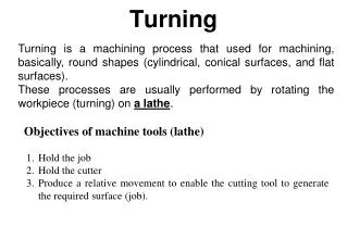
Feed The feed of a lathe may be defined as the distance the cutting tool advances along the length of the work for every revolution of the spindle.
Feed For example, if the lathe is set for a 0.4 mm feed, the cutting tool will travel along the length of the work 0.4 mm for every complete turn that the work makes. So the unit of feed (F) is mm/rev.
Depth of Cut Depth of cut is the difference in height between machined surface and the work surface. See Fig.1.12