Download
1 / 23
230 likes | 320 Views
E. Tasdelen 1 , H. Unbekannt 1 , M. Yildirim 1 , K. Willner 1 and J. Oberst 1,2. Implementation of a Self-Consistent Stereo Processing Chain for 3D Stereo Reconstruction of the Lunar Surface . 1 Department of Geodesy and Geoinformation Science, Technical University of Berlin

E N D
E. Tasdelen1, H. Unbekannt1, M. Yildirim1, K. Willner1 and J. Oberst1,2 Implementation of a Self-Consistent Stereo Processing Chain for 3D Stereo Reconstruction of the Lunar Surface 1 Department of Geodesy and Geoinformation Science, Technical University of Berlin 2 German Aerospace Center (DLR)
Motivation The department for Planetary Geodesy at TU Berlin is developing routines for photogrammetric processingof planetary image data to derive 3D representations of planetary surfaces. Aim: An independent generic 3D reconstruction pipeline Integrated Software for Imagers and Spectrometers(ISIS)developed by USGS Flagstaff, was chosen as a prime processing platform and tool kit. Image Matching 3D Point Calculation DTM Interpolation Visualization
Matching Software Overview of the software Stereo Images Matching Software TP File Parameters • Supports multithreading • Improved performance • Memory management for large images • Image formats • Vicar, ISIS cube, TIFF
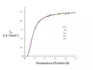
Matching Algorithms Area-based Matching (ABM) source: Rodehorst, 2004 Reference Image Search Image • Normalized Cross-Correlation (NCC) • where is covariance are variances
Matching Algorithms Least-Squares Matching (LSM): source: Bethmann et al., 2010 Reference Patch Compared Patches • Functional Model: Projective transformation f(x,y) + e(x,y) = g(x’,y’) • Transformation Model: a0 + a1x’ + a2y’ x = 1 + c1x’ + c2y’ x = a0 + a1x’ + a2y’ y = b0 + b1x’ + b2y’ b0 + b1x’ + b2y’ y = 1 + c1x’ + c2y’
Matching Types • Type1:Matching images without pre-processing • Same search space for each pixel • Type2:Coarse-to-fine hierarchical matching • Results from the pyramids override the search space boundaries
GRIDDING Matching Types • Type3:Grid-based matching • Grid-based projectivetransformation
Blunder Detection • The main reasons of blunders • occlusions, depth discontinuities, repetitive patterns, inadequate texture, etc. • Filters • Epipolar Check: With the help of epipolar geometrical relation, all the matched points are controlled and the distances of the points to the corresponding epipolar lines are calculated. Points exceeding a set threshold distance to the epipolar line are discarded. Epipolar Error Check Epipolar Relation
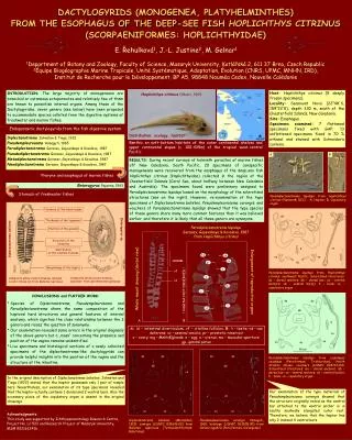
Blunder Detection • Overlapping Area Check: divide the reference image into regular sized grids and check if there are adequate numbers of tie-points within each grid. (a-b) left and right pair of stereo images, (c) actual overlapping area visualized on the left image, (d-f) grids with different sizes on the left image (300, 200 and 100 from d to f, respectively)
N 150PX 49750593 correspondences -500PX 1km LRO NAC Images for Copernicus Crater Resulting Disparity Map
3D Point Calculation • Forward Ray Intersection • Computation of spatial object coordinatesX from measured image points x and x’ as well as the camera matrices P and P’. source: Rodehorst, 2004
Blunder Detection • Filters on 3D point data • Octree Filter: uses octree data structure created from 3D point cloud data. • Nodes with low density, containing only few points, are considered as noise source: Wang, 2012
Blunder Detection • Filters on 3D point data • Delaunay Triangles: Each point is connected by lines to its closest neighbors, in such a way • The points which contributes triangles with edge length exceeding a threshold indicates the possible outliers.
1: X Y Z 2: X Y Z 3: X Y Z 4: X Y Z 5: X Y Z [...] n: X Y Z Conversion: from 3D Coordinates (Body-centric) to Map Coordinates DTM Interpolation • 3D point coordinates are first map-projected to a grid based images • Colliding points are interpolated • IDW, nearest neighbor, mean or median • A customized search radius can be applied to define the pixel value.
Visualization Tool • Main Challenges: • Rendering capabilities of graphics hardware • Limited to several millions of primitives per second • Geometry throughput effects the performance • Tremendous size of data does not fit into memory • Ex: 15km x 15km area with 1.5m res. > 5 GB of data, simply cannot be placed into memory at once [1] source: Wang, 2012
Visualization Tool • Level Of Detail (LOD) Algorithm • Decreasing the complexity of the object with the increasing distance to the viewer source: Bekiaris, 2009
Visualization Tool • Level Of Detail (LOD) Algorithm • Based on Quad Trees Each segment is called as a chunk source: Ulrich, 2002 Surface Representation Simplification • Each child chunk represent a more detailed version of one of its parents quarters
Visualization Tool • Rendering wrt. viewing direction LOD 2 LOD 1 Viewer LOD 0 Representation
N Landing Module 72.195 km
N Landing Module ~1000m The position of Apollo 17 landing module @Landing Module
N Landing Module ~1000m The position of Apollo 17 landing module @Landing Module
N A look towards south from the position of Apollo 17 landing module
N A look towards north from the position of Apollo 17 landing module


![>> W1=[1 1 1 1;1 -j -1 j;1 -1 1 -1;1 j -1 -j] W1 =](https://cdn1.slideserve.com/3227081/slide1-dt.jpg)