Download
1 / 56
560 likes | 658 Views
RAM Basics. Anselmo Lastra. Topics. VGA timing project Deadline Thursday Class time change Semester project topics RAMs. Class Time. Preference for keeping TTh Unfortunately, no open time for all. Projects. Some have project already Polygon pipeline

E N D
RAM Basics Anselmo Lastra
Topics • VGA timing project • Deadline Thursday • Class time change • Semester project topics • RAMs
Class Time • Preference for keeping TTh • Unfortunately, no open time for all
Projects • Some have project already • Polygon pipeline • Stopping points: Gouraud, texturing, etc. • Ray caster/tracer • Similar possible milestones • Can share common parts
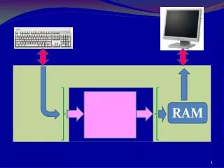
Simple Hdw View of RAM • Some capacity 2k • k bits of address lines • Often multiplexed • Maybe have read line, clock, chip select • Have a write enable line
Reading • Setup address lines • Activate enable, read/write line • Data available after specified amt of time
Writing • Setup address lines • Setup data lines • Activate write line
Static vs Dynamic RAM • SRAM vs DRAM • DRAM stores charge in what’s essentially capacitor • Disappears over short period of time • Must be refreshed (rewritten/recharged) • SRAM easier to use • Faster • More expensive per bit • Smaller sizes
Structure of SRAM • Control logic • One memory cell per bit • Cell consists of one or more transistors • Not really a latch made of logic • Logic equivalent
Bit Slice • Cells connected to form 1 bit position • Word Select gates one latch from address lines • Note it selects Reads also • B (and B not) set by R/W, Data In and BitSelect • Funny thing here when you write. What is it?
Bit Slice can Become Module • Basically bit slice is a X1 memory • Next
16 X 1 RAM • Now shows decoder
Tri-State • Have three states: H, L, and Hi-Z • High impedance • Behaves like no output connection if in Hi-Z state • Allows connecting multiple outputs
Multiplexed with Hi-Z • Normal behavior is blue area
Row/Column • If RAM gets large, there is a large decoder • Also run into chip layout issues • Larger memories usually “2D” in a matrix layout • Next Slide
16 X 1 as 4 X 4 Array • Two decoders • Row • Column • Address just broken up • Not visible from outside
Change to 4 X 2 RAM • Minor change in logic • Also pinouts
Realistic Sizes • Imagine 256K memory as 32K X 8 • One column layout would need 15-bit decoder with 32K outputs! • Can make a square layout with 9-bit row and 6-bit column decoders
SRAM Performance • Current ones have cycle times in low nanoseconds (say 2.5ns) • Used as cache (typically offchip secondary cache) • Sizes up to 8Mbit or so for fast chips
Using SRAM on Spartan II • Recall block SRAM available on chip • 11 4Kb blocks • Configured in many ways (table)
Using from Verilog • Instantiate a block (here called R1) RAMB4_S8_S8 R1 (.DOA (data_a), .DOB (data_b), .ADDRA (addr_a), .ADDRB (addr_a), .CLKA (clk), .CLKB (clk), .DIA (data_in), .DIB (data_in), .ENA (ena), .ENB (enb), .RSTA (rsta), .RSTB (rstb), .WEA (wea), .WEB (web));
Can Initialize • Have to do it two ways, one for simulator, another for hardware //synthesis attribute INIT_00 of R1 is "08192A3B4C5... total of 256 bits (64 hex characters)..." //synthesis attribute INIT_01 of R1 is "08192A3B4C5D6E7F08192A3B4C5D6E7F08192A3B4C5D6E7F08192A3B4C5D6E7F“ // Up to INIT_0F • Above is for hardware (next software)
For Simulation //synopsys translate_off defparam R1.INIT_00 = 64'h08192A3B4C5D6E7F08192A3B4C5D6E7F08192A3B4C5D6E7F08192A3B4C5D6E7F; // 256-bit hex value defparam R1.INIT_01 = 64'h08192A3B4C5D6E7F08192A3B4C5D6E7F08192A3B4C5D6E7F08192A3B4C5D6E7F; // 256-bit hex value ... defparam R1.INIT_0F = 64'h08192A3B4C5D6E7F08192A3B4C5D6E7F08192A3B4C5D6E7F08192A3B4C5D6E7F; // up to INIT_0F //synopsys translate_on
Look at Test Code • My RAM loading example from undergrad class http://www.cs.unc.edu/~lastra/comp190/Assignments/block_ram_C.txt
Dynamic RAM • Capacitor can hold charge • Transistor acts as gate • No charge is a 0 • Can add charge to store a 1 • Then open switch (disconnect) • Can read by closing switch • Explanation next
Precharge and Sense Amps • You’ll see “precharge time” • B is precharged to ½ V • Charge/no-charge on C will increase or decrease voltage • Sense amps detect this
DRAM Characteristics • Destructive Read • When cell read, charge removed • Must be restored after a read • Refresh • Also, there’s steady leakage • Charge must be restored periodically
DRAM Read Signaling • Lower pin count by using same pins for row and column addresses Delay until data available
DRAM Refresh • Many strategies w/ logic on chip • Here a row counter
CAS Before RAS • Set column address • Apply CAS first (opposite of RW) • Then toggle RAS enough times to cycle through row addresses • On-board refresh counter applies the row addresses
Timing • Say need to refresh every 64ms • Distributed refresh • Spread refresh out evenly over 64ms • Say on a 4Mx4 DRAM, refresh every 64ms/4096=15.6 us • Total time spent is 0.25ms, but spread • Burst refresh • Same 0.25ms, but all at once • May not be good in a computer system • Refresh takes 1 % or so of total time
Bidirectional Lines • One set of data pins • Used as input for write • As output for read • Tri-state • Makes sense because don’t need both at once
Page Mode DRAM • DRAMs made to read & write blocks • Example • Assert RAS, leave asserted • Assert CAS multiple times to read sequence of data • Similar for writes
Synchronous DRAM (SDRAM) • Common type in PCs late-90s • Burst transfers • Multiple banks • Pipelined • Start read in one bank after another • Come back and read the resulting values one after another
SDRAM on Xess Board • Relatively small at 128Mbits • 2M X 4 banks X 16 bits • Refresh every 64ms • Supports pipelining • Bidirectional data lines • Detailed info in a few slides
DDR DRAM • Double Data Rate SDRAM • Transfers data on both edges of the clock • Currently popular
RAMBUS DRAM (RDRAM) • Another attempt to alleviate pinout limits • Many (16-32) banks per chip • Made to be read/written in packets • Up to 400MHz bus speeds • But DDR doing very well also
DRAM Controllers • Very common to have circuit that controls memory • Handles banks • Handles refresh • Multiplexes column and row addresses • RAS and CAS timing • Northbridge on PC chip set
Next: Specifics on Our Chip • Protocol for reading/writing • Activate row first • Then read/write with column • Initialization • Setting parameters