Download
1 / 13
150 likes | 476 Views
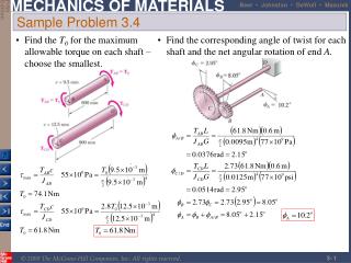
Sample Problem 3.4. Find the T 0 for the maximum allowable torque on each shaft – choose the smallest. Find the corresponding angle of twist for each shaft and the net angular rotation of end A. Determine torque applied to shaft at specified power and speed,.

E N D
Sample Problem 3.4 Find the T0 for the maximum allowable torque on each shaft – choose the smallest. Find the corresponding angle of twist for each shaft and the net angular rotation of end A.
Determine torque applied to shaft at specified power and speed, Find shaft cross-section which will not exceed the maximum allowable shearing stress, Design of Transmission Shafts • Principal transmission shaft performance specifications are: • power • speed Designer must select shaft material and cross-section to meet performance specifications without exceeding allowable shearing stress.
The derivation of the torsion formula,assumed a circular shaft with uniform cross-section loaded through rigid end plates. Experimental or numerically determined concentration factors are applied as Stress Concentrations The use of flange couplings, gears and pulleys attached to shafts by keys in keyways, and cross-section discontinuities can cause stress concentrations Fig. 3.32 Stress-concentration factors for fillets in circular shafts.
With the assumption of a linearly elastic material, The integral of the moments from the internal stress distribution is equal to the torque on the shaft at the section, Plastic Deformations If the yield strength is exceeded or the material has a nonlinear shearing-stress-strain curve, this expression does not hold. Shearing strain varies linearly regardless of material properties. Application of shearing-stress-strain curve allows determination of stress distribution.
At the maximum elastic torque, As the torque is increased, a plastic region ( ) develops around an elastic core ( ) As , the torque approaches a limiting value, Elastoplastic Materials
Plastic region develops in a shaft when subjected to a large enough torque. On a T-f curve, the shaft unloads along a straight line to an angle greater than zero. Residual stresses found from principle of superposition Residual Stresses When the torque is removed, the reduction of stress and strain at each point takes place along a straight line to a generally non-zero residual stress.
A solid circular shaft is subjected to a torque at each end. Assuming that the shaft is made of an elastoplastic material with and determine (a) the radius of the elastic core, (b) the angle of twist of the shaft. When the torque is removed, determine (c) the permanent twist, (d) the distribution of residual stresses. Example 3.08/3.09 SOLUTION: • Solve Eq. (3.32) for rY/c and evaluate the elastic core radius Solve Eq. (3.36) for the angle of twist Evaluate Eq. (3.16) for the angle which the shaft untwists when the torque is removed. The permanent twist is the difference between the angles of twist and untwist Find the residual stress distribution by a superposition of the stress due to twisting and untwisting the shaft
SOLUTION: • Solve Eq. (3.32) for rY/c and evaluate the elastic core radius Solve Eq. (3.36) for the angle of twist Example 3.08/3.09
Evaluate Eq. (3.16) for the angle which the shaft untwists when the torque is removed. The permanent twist is the difference between the angles of twist and untwist Find the residual stress distribution by a superposition of the stress due to twisting and untwisting the shaft Example 3.08/3.09
Previous torsion formulas are valid for axisymmetric or circular shafts For uniform rectangular cross-sections, At large values of a/b, the maximum shear stress and angle of twist for other open sections are the same as a rectangular bar. Torsion of Noncircular Members Planar cross-sections of noncircular shafts do not remain planar and stress and strain distribution do not vary linearly
Summing forces in the x-direction on AB, shear stress varies inversely with thickness Compute the shaft torque from the integral of the moments due to shear stress Angle of twist (from Chapter 11) Thin-Walled Hollow Shafts
Example 3.10 Extruded aluminum tubing with a rectangular cross-section has a torque loading of 2.7 kNm. Determine the shearing stress in each of the four walls with (a) uniform wall thickness of 4 mm and wall thicknesses of (b) 3 mm on AB and CD and 5 mm on CD and BD. SOLUTION: • Determine the shear flow through the tubing walls. Find the corresponding shearing stress with each wall thickness .
Example 3.10 • Find the corresponding shearing stress with each wall thickness. With a uniform wall thickness, SOLUTION: • Determine the shear flow through the tubing walls. With a variable wall thickness