Download
1 / 19
190 likes | 322 Views
Effects of Changes in Shaft Load. Shaft load is doubled – I a cos θ i and E f sin δ must double. Effects of Changes in Shaft Load.

E N D
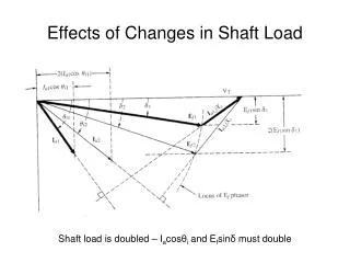
Effects of Changes in Shaft Load Shaft load is doubled – Iacosθi and Efsinδ must double
Effects of Changes in Shaft Load Since Field Excitation is constant, Ef traces a circular arc, δ increases θi decreases, increasing the power factor – continues until δ=90 -- pullout
Effects of Changes in Field Excitation Voltage on Synchronous-Motor Performance Apply step changes to Ef
Effects of Changes in Field Excitation Voltage on Synchronous-Motor Performance Efsinδ must be constant Apply step changes to Ef
Effects of Changes in Field Excitation Voltage on Synchronous-Motor Performance • Increasing the strength of the magnets should cause a closer pole alignment and a smaller power angle. • Assuming a constant shaft load, • apply a step increase to Ef • Efsinδ increases, the rotor accelerates • angle δ decreases until Efsinδ has the same value as before (synchronous speed)
Effects of Changes in Field Excitation Voltage on Synchronous-Motor Performance Iacosθ constant Efsinδ constant Apply step changes to Ef
Effects of Changes in Field Excitation Voltage on Synchronous-Motor Performance • For constant shaft load, • P is proportional to Efsinδ • Ef1sinθ1 = Ef2sinθ2 = Ef3sinθ3 = Efsinθ • Locus of the tip of the Ef phasor is parallel to the VT phasor • P is proportional to Iacosθ • Ia1cosθ1 = Ia2cosθ2 = Ia3cosθ3 = Iacosθ • Locus of tip of the Ia phasor is perpendicular to the VT phasor
Effects of Changes in Field Excitation Voltage on Synchronous-Motor Performance Iacosθ constant Efsinδ constant Apply step changes to Ef
Effects of Changes in Field Excitation Voltage on Synchronous-Motor Performance • IMPORTANT!!!! • Increasing the excitation from Ef1 to Ef3 caused the angle in the current phasor (and hence the power factor) to go from lagging to leading! • Normal excitation when power factor = 1 • Excitation greater than normal is known as overexcitation • Excitation less than normal is known as underexcitation
Effects of Changes in Field Excitation Voltage on Synchronous-Motor Performance Iacosθ constant Power factor changes from lagging to leading Efsinδ constant Apply step changes to Ef
V Curves • Plot armature current as a function of field current or armature current as a function of excitation voltage.
Stability Limit is where angle δ = -90° -- the rotor is still synchronized
V-Curves continued • Constant-Load V-Curves can be plotted from laboratory data, phasor diagrams, or from the following expression
Example 8.2 • Referring to the V-curve for 100% load, determine • a) the minimum value of excitation that will maintain synchronism 98V 100% rated load
Example 8.2 continued • b) using Eq. (8 – 16)
Example 8.2 continued • Repeat (a) using Eq. (8-21) Make the quantity under the radical = 0 for minimum excitation
Example 8.2 continued • d) the power angle if the field excitation voltage is increased to 175% of the stability limit determined in (c).