Download
1 / 14
140 likes | 256 Views
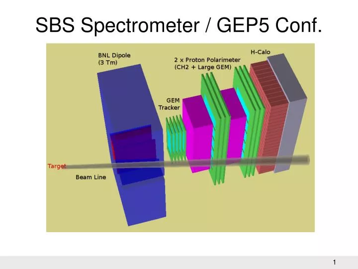
SBS Spectrometer / GEP5 Conf. Tracking Requirements. … and modular: reuse in different geometrical configuration. MPGD = Micro Pattern Gas Detector (GEM, Micromegas …). GEM for SBS. Proposed Layout for SBS: Several chamber modules of 40x50 cm 2 each Standard 3 GEM foils

E N D
Tracking Requirements … and modular: reuse in different geometrical configuration MPGD = Micro Pattern Gas Detector (GEM, Micromegas …)
GEM for SBS • Proposed Layout for SBS: • Several chamber modules of 40x50 cm2 each • Standard 3 GEM foils • 2D Readout plane, 0.4 mm pitch • Last GEM HV layer segmented and read-out (0.5 mm pitch) • Approx. 70000 channels Gain ~ 20^3 = 8000 2D Readout perpendicular (x,y) and/or +/- 30 degree (u,v) ? Second is certainly more demanding for the extraction of the strips
SBS Front Tracker Project few months delay BA: Gas system + Electronics (FE chips) CA: Mechanics + Test + MC + Slow Control GE: Electronics ISS/ROME: Prototyping, Test, Digitization + Reconstruction, Evaluate Si, Coordination
Prototyping • 3 10x10 cm2 chambers (one under test) • Working on 40x50 cm2 module, with minimum dead area in the frame (minimum frame thickness); main practical issues: • Each GEM foil has two HVs (one on each GEM side). Each GEM side must be segmented in order to suppress discharge spreading; each segment is connected to the HV power supply by a protection resistor • Gas in/out-lets in tiny frames (2-3 mm thickness) • Thousands readout strip extraction • Front-End electronics position and anchor
GEM HV sectors and resistors GEM requires 10x10 cm2 sectors for HV distribution Use surface mounted HV resistors Distribute HV from two sides Gluing GEM foil on the frame may be a problem practical test in preparation! Red and Green are the 2 HV levels serving one GEM foils Resistors will be placed on the two sides
Electronics Front-End at 90° Electronics will be placed at 90° respect to the readout plane on 2 side of the frame. Some holes (bottom-left) will permit the passage (and protection) of the flat on the readout side. The width of the frame shall be as small as possible (working on 5 mm). • Connector type is a constraint in possible 90° configurations • +/-30° strips extraction an unsolved problem! Flex close to 90° bending, protected by the frame 2x2 chamber configuration
Visual inspection back-light board HV single foil testing station Clean Room Tools and Facilities • Facilities available in clean room: • Visual Inspection • HV test • Foil Cleaning • Stretching, gluing and heating Assembling the GEM chambers parts require a careful quality controlled procedure: inspecting cleaning testing(0) stretching gluing heating testing(1)
Real Prototype 0 • First 10x10 prototype under cosmic test • Using 70/30 Ar/CO2 gas mixture • 7 Independent HV levels up to about 4200 V Using temporary “Genova” electronics (PESA + ALTRO) from ALICE Bought about 620 APV25 analog chips for the final electronics (about 80000 channels)
HV Slow Control Use 7 HV independent levels to study the chamber performance HV management is not trivial! Keep noise at adequate level: use low pass filters on HV lines
“fake” prototype Testing solutions and alternatives on a fake 40x50 cm2 GEM chamber with asymmetric frame (5 mm one 2 L sides, 5 cm on the opposite L sides). • Gain experience on kapton gluing • Test mechanics • Optimize position of the resistors, gas pipes, readout fanout
Mechanical Analysis in progress • Assumptions: • 50 kV/cm felectrostatic field • GEM foil made of Kapton: • Young module: 5.38*109 N/m2 • Poisson module 0.32 • Shear module 0.35*109 N/m2 • Density1.4 g/cm3 • Fram in STESALITE • Young module 244*109 N/m2 • Poisson module 0.29 • Shear module (evaluated by the softwarE)
FEM of single GEM foil • STESALITE frame of 40x50 cm2, 5 mm width, 2 mm thick Deformation well below tolerance (5% of 2 mm) Limiting frame widths seems to be the HV paths, resistors and readout
Planned activities for the next few months • Finalize the cosmic tests to characterize the prototyped telescope • Finalize the design of the 40x50 GEM foil and readout, then order them • Development of the electronics (Genova), based on COMPASS • First July we have to apply for the 2010 INFN funding.It is fundamental to have a “reasonable” view of the future of the SBS project